
Modern electronics, from LED drivers to automotive inverters and 5G base stations, generate significant heat in compact spaces. Traditional FR4 boards struggle with heat dissipation, leading to component failures and reduced system reliability.
Aluminum PCB technology offers a solution by replacing FR4 with a thermally conductive aluminum base, improving heat transfer by 600× and reducing junction temperatures by 30–50°C. This helps extend component lifespans by 2–5×.
At HILPCB, we provide a wide range of PCB solutions, including aluminum, metal core, heavy copper, HDI, flexible, and more. Our expertise in PCB manufacturing ensures reliable thermal and electrical solutions tailored to your specific needs.
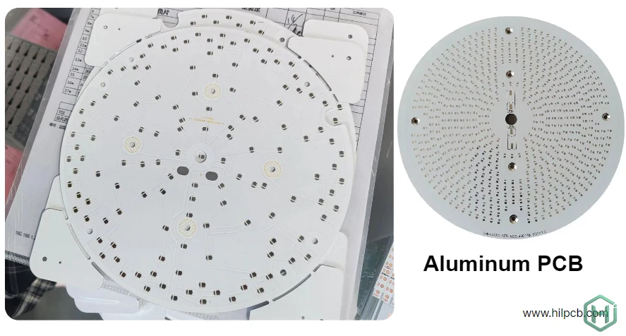
What Is an Aluminum Circuit Board and How It Improves Thermal Performance
An aluminum PCB replaces traditional FR4 with an aluminum alloy base, creating a three-layer construction optimized for thermal management:
Copper Circuit Layer (1–10 oz) carries electrical signals and distributes power. Copper thickness selection depends on current requirements—standard 1–2 oz for signals, 3–6 oz for power distribution, and up to 10 oz heavy copper for extreme applications exceeding 50A.
Dielectric Layer (50–200 µm thick) electrically isolates the copper circuit from the metal base while conducting heat vertically. This layer uses polymer composites filled with ceramic particles, achieving thermal conductivity of 1–5 W/mK—dramatically higher than FR4's 0.3 W/mK.
Aluminum Base (1.0–3.0 mm) provides three critical functions: heat spreading with 200 W/mK thermal conductivity, mechanical support for dimensional stability, and electromagnetic shielding for EMI reduction.
Heat flows vertically through the thin dielectric layer, then spreads laterally across the aluminum substrate before dissipating to heatsinks or ambient air. This architecture creates a thermal highway maintaining safe component temperatures even under continuous high-power operation.
Key Thermal Advantages of Aluminum Circuit Boards for High-Power Electronics
Superior Heat Dissipation Compared to FR4 Boards
A typical aluminum substrate PCB with 2 W/mK dielectric and 2mm aluminum base exhibits thermal resistance of approximately 1–2 °C/W for a 1cm² hot spot. The same geometry in FR4 shows thermal resistance exceeding 20 °C/W—a 10–20× performance difference.
For a 10W component, this translates to junction temperature rise of just 10–20°C versus 200°C+ in FR4—the difference between reliable operation and immediate thermal failure.
Longer Component Lifespan Through Efficient Cooling
Industry accelerated life testing demonstrates exponential relationships between operating temperature and component longevity. High-brightness LEDs operating at 85°C junction temperature achieve 50,000+ hour lifetimes. The same LEDs at 125°C fail in under 10,000 hours—an 80% reduction in operational life.
For power semiconductors, every 10°C temperature increase approximately halves expected lifetime according to Arrhenius acceleration models. By maintaining lower junction temperatures, aluminum PCB designs deliver 2–5× longer component lifespans, reducing warranty costs and improving customer satisfaction.
Reliable Thermal Cycling Performance in Harsh Environments
Temperature cycling generates mechanical stress from coefficient of thermal expansion (CTE) mismatches between materials. Aluminum (CTE 23 ppm/°C) matches copper (17 ppm/°C) far better than FR4 (70+ ppm/°C z-axis). The rigid aluminum base also constrains warping during temperature excursions.
These factors give aluminum circuit board constructions superior reliability through thousands of thermal cycles—critical in automotive applications experiencing daily temperature swings from -40°C to +125°C.
Best Materials for Aluminum Circuit Board Manufacturing
Top Aluminum Alloys Used in PCB Substrates
- AL1060 Aluminum: Cost-effective, good thermal conductivity (~150 W/mK), used in low-power applications.
- AL3003 Aluminum: Moderate strength and thermal conductivity (~160 W/mK), suitable for general LED lighting.
- AL5052 Aluminum: Excellent corrosion resistance, good thermal conductivity (~170 W/mK), ideal for high-power LED and automotive applications.
- AL6061 Aluminum: Superior strength and thermal conductivity (~170–180 W/mK), used for demanding applications like high-power electronics and automotive systems.
Dielectric Layer Options
- Standard Thermal (1.5–2.0 W/mK): Cost-effective, suitable for moderate heat loads.
- High-Performance (3–5 W/mK): For critical thermal demands, offers better heat management.
- Ultra-High Conductivity (5+ W/mK): For extreme applications like aerospace or military use.
Aluminum Circuit Board Design Guidelines for Thermal and Electrical Efficiency
Effective Thermal Via Design Techniques
Thermal vias create vertical heat paths from component footprints to the aluminum base. Effective design uses 0.3–0.5mm diameter vias with 1 oz copper plating, spaced 0.8–1.2mm apart beneath high-power components.
Hexagonal patterns maximize coverage for circular components like LEDs. Via-in-pad placement improves thermal performance but requires via filling or capping processes to prevent solder wicking during assembly.
Component Placement Strategies for Optimal Heat Distribution
Distribute high-power components across board area rather than concentrating heat in small regions. Maintain minimum 10–15mm spacing between components dissipating >2W each to prevent thermal coupling.
Position temperature-sensitive components (voltage references, precision resistors, oscillators) at least 20mm away from primary heat sources. The aluminum substrate's heat spreading means thermal effects extend several centimeters from power components.
Copper Trace Design for High-Current Applications
Trace width calculations follow IPC-2221 guidelines but benefit from enhanced cooling provided by the aluminum substrate. This allows 20–30% higher current density for equivalent temperature rise compared to FR4 designs.
For high-current paths exceeding 10A, use copper pours or wide traces (>3mm) to minimize voltage drop and resistive heating. When currents exceed 30–50A, integration with heavy copper PCB technology provides necessary current capacity.
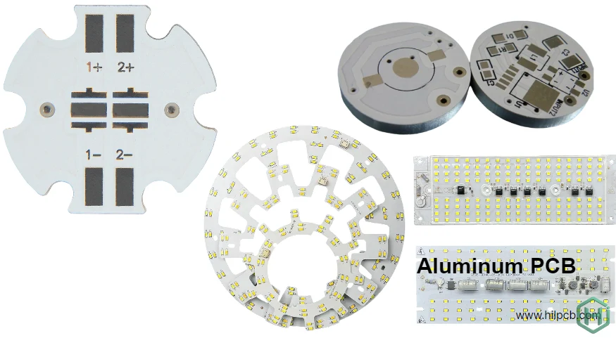
Top Applications of Aluminum Circuit Boards in Modern Industries
LED Lighting Systems and High-Power Arrays Automotive Electronics and EV Power Systems Power Electronics and Industrial Equipment Consumer Electronics Renewable Energy Systems Telecommunications and RF Systems Medical Devices and Equipment Lighting for Commercial and Residential Use Smart Home and IoT Devices Aerospace and Military Electronics
PCB Manufacturing Capabilities at HILPCB
At HILPCB, we offer a comprehensive range of PCB solutions, not limited to just Aluminum PCBs. Our capabilities cover all types of PCBs, including FR4, Aluminum PCB, Metal Core PCB (MCPCB), Heavy Copper PCB, Flexible PCB, and HDI PCB. Whether you need standard, high-performance, or custom solutions, we have the expertise to deliver.
Materials
- Aluminum Alloys: We use AL1060, AL3003, AL5052, and AL6061 aluminum alloys with thermal conductivity from 150 W/mK to 180 W/mK, suitable for various thermal management needs in applications such as LED lighting, automotive, and power electronics.
- Other Materials: We also manufacture PCBs using FR4, Polyimide, PTFE, and Rogers materials for high-frequency and high-speed applications.
Copper Weights
- Standard: 1–2 oz for signal traces.
- Power Distribution: 3–6 oz for higher current capacity.
- Heavy Copper: Up to 10 oz for extreme current applications (such as motor drives, power supplies, etc.). Learn more about our heavy copper PCB options.
Surface Finishes
- HASL, lead-free HASL, ENIG, immersion silver, OSP, and more. We also offer white/black solder mask options optimized for LED applications and other custom requirements.
Quality Standards
- ISO 9001, UL, IPC-6012 Class 2/3, RoHS/REACH, and IATF 16949 (for automotive applications).
Our PCB manufacturing process ensures consistent quality, full material traceability, and comprehensive test documentation to meet customer qualification standards.
FAQ About Aluminum PCBs
Q1: What is the difference between aluminum PCB and metal core PCB?
Aluminum PCB specifically uses aluminum alloy as the base substrate. Metal core PCB is a broader term encompassing aluminum, copper, or steel substrates. Aluminum accounts for 95%+ of metal core PCBs due to optimal balance of thermal performance, weight, and cost.
Q2: How much temperature reduction vs FR4?
Typical aluminum PCB designs reduce component junction temperatures by 30–50°C compared to equivalent FR4 implementations for the same power dissipation and board area. Actual results depend on power density, board design, thermal interface quality, and ambient conditions.
Q3: Can I use standard PCB design software?
Yes, aluminum PCB designs use standard EDA tools (Altium, Eagle, KiCad, etc.). The key difference is stackup definition—specify the dielectric and aluminum base layers correctly. Most manufacturers provide stackup templates for their material options.
Q4: Are aluminum PCBs compatible with SMT assembly?
Yes, fully compatible with automated SMT assembly processes. The higher thermal mass requires slight reflow profile adjustments—typically 5–10°C higher peak temperature or 10–20 seconds longer time above liquidus to ensure complete solder joint formation.
Q5: What is the maximum board size?
Standard production equipment handles aluminum PCBs up to 500×600mm (20"×24"). Larger sizes require custom processing and handling. Practical limits also depend on thickness—2.0mm aluminum in 600mm length may require support during handling to prevent bending.