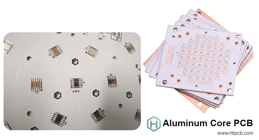
High-power applications, such as LED lighting, automotive electronics, and power systems, generate significant heat that must be effectively dissipated. Aluminum core PCBs offer a superior solution by providing excellent thermal conductivity, ensuring safe operating temperatures for reliable performance.
At HILPCB, we offer comprehensive PCB manufacturing and assembly services tailored to optimize thermal efficiency, performance, and reliability. Whether you need solutions for LED systems, automotive electronics, or power applications, we deliver high-quality results. Our expertise in metal core PCB manufacturing ensures consistent thermal performance from prototype to mass production, meeting the demands of even the most challenging thermal environments.
Why Aluminum Core PCB Outperforms Traditional FR4
The fundamental difference lies in thermal architecture. FR4 forces heat through a low-conductivity substrate before reaching ambient air—creating a thermal bottleneck that causes temperatures to spike. Aluminum core PCB replaces this bottleneck with a metal highway conducting heat 600× faster.
Thermal Performance Comparison:
| Parameter | FR4 PCB | Aluminum Core PCB |
|---|---|---|
| Thermal Conductivity | 0.3 W/mK | 1–5 W/mK (dielectric) + 200 W/mK (Al) |
| Junction Temp Rise | +40–60°C | +10–25°C |
| Component Lifespan | Baseline | 2–5× longer |
| Power Density Capacity | <1W/cm² | 3–10W/cm² |
For a 10W LED, this translates to junction temperature of 65°C versus 100°C in FR4—the difference between 50,000-hour lifetime and 10,000-hour premature failure.
The aluminum substrate provides three critical functions: vertical heat conduction from components, lateral heat spreading across the board surface, and mechanical rigidity preventing warpage. A thin dielectric layer (50–200µm) maintains electrical isolation while conducting heat vertically with minimal resistance.
Construction Details:
- Copper Layer: 1–10 oz for circuit traces and power distribution
- Dielectric Layer: Ceramic-filled polymer (1–5 W/mK thermal conductivity)
- Aluminum Base: 1.0–3.0mm substrate (5052 or 6061 alloy)
For high-current applications exceeding 50A, integration with heavy copper PCB technology provides both electrical capacity and enhanced thermal spreading.
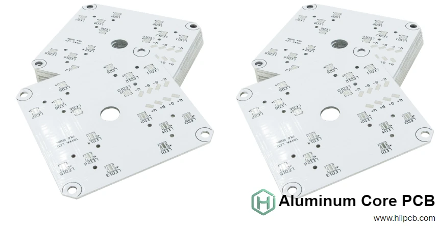
Key Applications Driving Aluminum Core PCB Demand
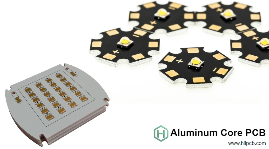
LED Lighting Systems
High-brightness LEDs convert only 30–40% of input power to light—the remaining 60–70% becomes heat concentrated in millimeter-scale junctions. Junction temperatures exceeding 85°C cause accelerated degradation, color shift, and catastrophic lumen depreciation.
Aluminum core PCB maintains LED temperatures below critical thresholds even at maximum drive currents. Applications include street lighting (80–150W arrays), automotive headlamps (30–60W), horticultural systems (100–400W), and architectural lighting. White solder mask reflects stray light, improving system efficiency by 5–10%.
Design Features:
- Thermal via arrays beneath each LED (12–20 vias, 0.4mm diameter)
- 2 oz copper spreading layer
- 1.5–2.0mm aluminum substrate
- 2.0 W/mK dielectric for cost optimization
Automotive Power Electronics
Modern vehicles contain 50–150 electronic control units operating from -40 to +125°C. Engine compartments exceed 125°C ambient while power electronics generate internal heat. Battery management systems, DC-DC converters, and inverters dissipate 20–200W in compact enclosures.
Aluminum base PCB technology provides reliable operation across automotive temperature ranges. The rigid aluminum substrate survives vibration per SAE J1455 standards while maintaining thermal performance through thousands of temperature cycles.
Electric vehicle inverters handling 50–200kW use specialized designs combining aluminum core sections for IGBTs with FR4 multilayer sections for control circuitry—a hybrid approach called aluminum clad PCB.
Industrial Power Supplies
Switch-mode power supplies, motor drives, and solar inverters benefit from integrated thermal management. MOSFETs and IGBTs switching at 100kHz–1MHz generate significant heat proportional to power throughput.
Aluminum core PCB enables compact 500W supplies in palm-sized packages versus twice the volume required for FR4 designs with external heatsinks. Efficiency improvements of 1–3 percentage points result from lower junction temperatures reducing conduction and switching losses.
Typical Specifications:
- 2.0mm aluminum substrate for heat spreading
- 3.0–4.0 W/mK high-performance dielectric
- 4–6 oz copper for high-current traces
- Via arrays beneath power semiconductors
Design Guidelines for Maximum Thermal Efficiency
Thermal Via Strategy
Thermal vias create critical vertical heat paths from component footprints to the aluminum substrate. Optimal design uses 0.3–0.5mm diameter vias with 1 oz copper plating, spaced 0.8–1.2mm apart in hexagonal arrays.
Via Count Guidelines:
- 1–2W components: 8–12 vias
- 3–5W components: 12–20 vias
- 5–10W components: 20–40 vias
10W components: Via-in-pad with epoxy filling
Via-in-pad placement eliminates lateral heat spreading distance but requires via filling to prevent solder wicking during assembly. HILPCB offers via filling services specifically for high-power applications.
Component Placement Optimization
Distribute high-power components across board area rather than concentrating heat. Maintain minimum 10–15mm spacing between components dissipating >2W to prevent thermal coupling where one device's heat raises ambient temperature for neighbors.
Position temperature-sensitive components (voltage references, precision resistors, crystal oscillators) at least 20mm from primary heat sources. The aluminum substrate's efficient heat spreading means thermal effects extend several centimeters from power devices.
Copper Weight Selection
Standard 1–2 oz copper suits signal traces and moderate power distribution. Power planes carrying 10–30A require 3–6 oz copper to minimize resistive heating. For extreme applications exceeding 50A, heavy copper PCB technology using 8–10 oz copper becomes necessary.
Thicker copper also improves lateral heat spreading from concentrated hot spots before vertical conduction through the dielectric layer. Wide copper pours beneath power components distribute heat across larger aluminum substrate area.
Dielectric Selection
Standard 1.5–2.0 W/mK dielectrics suit moderate heat loads (<3W/cm²) with 100–150µm thickness. High-performance 3–5 W/mK materials reduce thermal resistance 40–60% but cost 50–100% more—justified when power density or board area constraints demand maximum performance.
Thinner dielectrics (50–75µm) minimize thermal resistance but increase electrical stress, limiting voltage isolation. High-voltage applications (>500V) require 150–200µm thickness despite thermal performance sacrifice.
HILPCB Manufacturing Excellence
Our metal core PCB facility implements advanced process control ensuring consistent thermal performance:
Material Quality: Aluminum substrates undergo surface treatment (anodizing or conversion coating) improving adhesion. Incoming inspection verifies thermal conductivity, thickness, and composition before production.
Lamination Control: Vacuum lamination presses bond dielectric to aluminum under precise temperature (±2°C) and pressure (±10 PSI) control. Process monitoring ensures void-free interfaces critical for thermal performance.
Drilling Precision: Specialized carbide drill bits and optimized parameters for aluminum substrates prevent burr formation while maintaining dimensional accuracy (±0.05mm).
Testing Verification: Every production lot undergoes electrical testing, thermal imaging inspection, and dimensional verification. Sample boards receive thermal resistance measurement validating specifications.
Quality Certifications: ISO 9001, UL, IPC-6012 Class 2/3, RoHS/REACH compliance, and IATF 16949 for automotive applications. Complete material traceability supports customer qualification requirements.
Our PCB manufacturing facility delivers 5–7 day prototyping and 10–15 day production lead times with full engineering support from thermal analysis through volume manufacturing.