As a full-service PCB manufacturer, HILPCB builds a wide range of circuit board technologies—from standard FR4 boards to HDI, rigid-flex, and advanced flexible PCB solutions. Among them, Flex PCBs demand special attention to material behavior, bend mechanics, and controlled manufacturing tolerance.
This guide focuses on engineering-grade flex PCB specifications—helping product teams define constructions, materials, and stack-ups that ensure manufacturability, long-term reliability, and cost-efficiency. With expertise spanning flexible PCB engineering and polyimide material performance, HILPCB supports engineers from requirement definition through volume production.
Flex PCB Construction Types
Understanding available flexible circuit board constructions helps engineers select optimal configurations for specific applications. Each type offers distinct advantages and limitations.
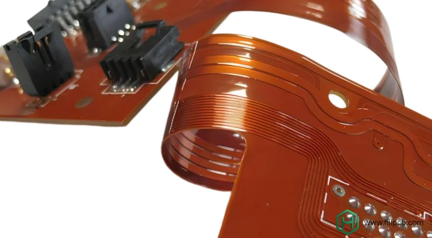
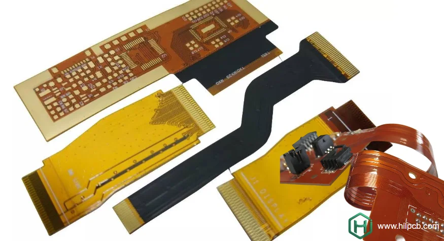
Single-Sided Flex PCB Simplest construction with copper on one side of polyimide substrate. Ideal for simple interconnects, LED strips, and low-density applications. Offers maximum flexibility and lowest cost. Limited to point-to-point connections without crossovers.
Double-Sided Flex PCB Copper layers on both sides with plated through-holes connecting them. Enables crossovers and increased routing density. Slightly reduced flexibility compared to single-sided but far more capable. Suitable for most moderate-complexity applications.
Multilayer Flex PCB Three or more copper layers with internal power/ground planes. Provides controlled impedance, EMI shielding, and maximum routing density. Reduced flexibility and higher cost justified for complex, high-speed designs. Typical configurations include 4-layer and 6-layer FPC boards.
Rigid-Flex PCB Combines flexible sections with rigid PCB regions in single assembly. Eliminates board-to-board connectors while providing stable component mounting areas. Optimal for complex 3D packaging and high-reliability applications.
Material Specifications and Properties
Material selection determines flex PCB performance across temperature, frequency, and mechanical stress. Understanding material properties enables informed specification decisions.
Polyimide Substrate Options Standard polyimide (Kapton HN) operates -200°C to +300°C with proven reliability. High-performance grades (Kapton E, UPILEX-S) offer enhanced dimensional stability for fine-pitch circuits. Our polyimide PCB expertise ensures optimal material matching to application requirements. Film thickness ranges from 12.5μm for ultra-thin applications to 125μm for maximum rigidity.
Copper Weight Selection Copper thickness directly impacts flexibility and current-carrying capacity. Rolled annealed copper (RA) provides superior flexibility for dynamic applications. Electrodeposited (ED) copper offers cost advantages for static-flex designs. Common specifications:
- ½ oz (18μm): Maximum flexibility, limited current capacity
- 1 oz (35μm): Standard specification, good flexibility
- 2 oz (70μm): High current capacity, reduced flexibility
Adhesive vs. Adhesiveless Traditional construction uses acrylic adhesive bonding copper to polyimide. Adhesiveless (two-layer cast) eliminates this layer, reducing thickness 15-25μm while improving thermal performance. Higher material cost justified for HDI applications requiring minimum thickness.
Coverlay Specifications Coverlay thickness typically matches base film (25-50μm). Acrylic adhesive provides good bonding with moderate heat resistance. Epoxy adhesive offers superior thermal performance for high-temperature applications. Laser-drilled openings enable fine-pitch pad access impossible with mechanical punching.
Electrical and Mechanical Specifications
Defining precise specifications ensures manufacturing excellence while meeting application requirements.
Line Width and Spacing Standard capabilities support 100μm (4 mil) lines and spaces. Advanced manufacturing achieves 75μm (3 mil) for high-density designs. Fine-pitch specifications require controlled processes and adhesiveless construction for best results.
Via Specifications Minimum via diameter relates to substrate thickness and capability. Standard through-hole vias: 200μm diameter with 100μm annular ring. Laser-drilled microvias enable HDI constructions: 100μm diameter possible. Via-in-pad designs require special plugging and planarization processes.
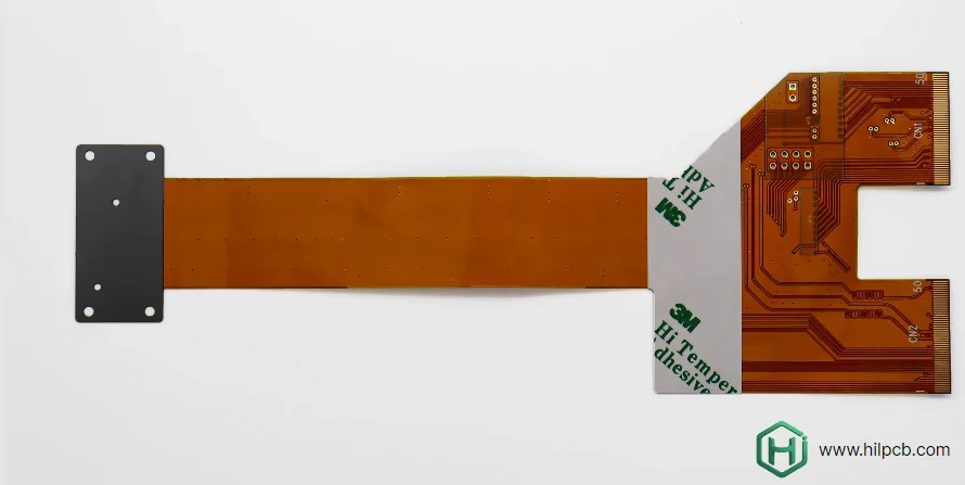
Bend Radius Requirements Dynamic flex (repeated bending): 10× total thickness minimum Static flex (one-time bend): 6× total thickness acceptable Zero-bend regions: Component areas and connectors require stiffeners
Surface Finish Options ENIG (Electroless Nickel Immersion Gold): Excellent solderability, flat surface, 5-10μm nickel, 0.05-0.15μm gold Immersion Silver: Cost-effective, good solderability, limited shelf life OSP (Organic Solderability Preservative): Lowest cost, requires careful handling Immersion Tin: Good solderability, suitable for assembly processes
HILPCB — Flex PCB Engineering Support
Flex PCB specification is not only about selecting materials and thicknesses—it's about ensuring long-term operational reliability under real-world stress. Factors such as copper grain direction, adhesive systems, impedance stability, thermal cycling, humidity exposure, and bend fatigue must align with the product’s intended lifecycle.
HILPCB provides comprehensive engineering and production support for flex circuits, including:
- Full construction range — single-sided, double-sided, multilayer, and rigid-flex
- Controlled-impedance and HDI capability — fine-line processing, microvias, and thin-core builds
- Material flexibility — RA/ED copper, adhesiveless structures, high-temperature polyimide
- Reliability validation — flex-cycle tests, AOI/ECT, dimensional measurement, thermal aging
- Manufacturability assurance — DFM reviews, stack-up optimization, yield-driven routing guidance
- Industry readiness — automotive, medical, aerospace, consumer and industrial deployments
- Supply-chain stability — rapid prototyping to scaled production with consistent specifications
With flex PCB manufacturing capabilities and seamless rigid-flex integration, HILPCB becomes a strategic partner—ensuring every flex circuit delivers the electrical performance, mechanical resilience, and product reliability your customers expect.
Frequently Asked Questions
Q1: What copper weight should I specify for my flex PCB? Specify ½ oz (18μm) for maximum flexibility in dynamic-flex applications. Use 1 oz (35μm) for standard applications balancing flexibility and current capacity. Choose 2 oz (70μm) only when high current demands outweigh flexibility requirements. Consult with manufacturers for optimization.
Q2: How do I determine appropriate bend radius for my design? Calculate minimum bend radius as 10× total thickness for dynamic flexing (repeated bending during operation). Static-flex applications (bent once during assembly) can use 6× total thickness. Include all layers, adhesives, and coverlay in thickness calculation.
Q3: What line width and spacing capabilities should I expect? Standard flex PCB manufacturing supports 100μm (4 mil) lines and spaces reliably. Advanced processes achieve 75μm (3 mil) with adhesiveless construction and controlled processing. Specify wider geometries when possible to improve yield and reduce cost.
Q4: When should I choose adhesiveless construction? Select adhesiveless construction when minimum thickness is critical (wearables, implantables), superior thermal performance required, or ultra-fine pitch geometries needed. Accept higher material cost for these performance advantages. Standard adhesive construction suits most applications.
Q5: How do surface finish choices affect flex PCB performance? ENIG provides best shelf life and solderability but adds cost and thickness. Immersion silver offers good performance at moderate cost. OSP minimizes thickness and cost but requires prompt assembly. Choose based on assembly timeline, storage requirements, and budget constraints.