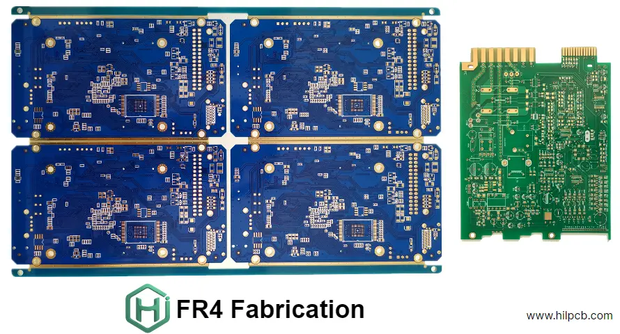
FR4 fabrication is the foundation of most modern printed circuit boards. If you are looking for a professional PCB manufacturer that can provide FR4 PCB fabrication and assembly services, you are in the right place. We specialize in high-quality FR4 PCB manufacturing, covering everything from prototype to full-scale production, with strong engineering support and competitive pricing.
What Is FR4 and Why It Matters in PCB Fabrication
FR4 is a glass-fiber epoxy laminate material that offers an excellent balance between mechanical strength, electrical insulation, and cost efficiency. It’s the most widely used PCB base material in electronic manufacturing today.
Typical properties of FR4 include:
- Dielectric constant (Dk): 4.2 – 4.8
- High insulation resistance
- Flame retardant (UL94-V0 rating)
- Good mechanical rigidity and moisture resistance
These characteristics make FR4 suitable for applications in consumer electronics, industrial automation, automotive systems, and communication devices. Whether you need a 2-layer prototype or a complex multilayer design, FR4 provides the versatility and reliability required for both signal integrity and long-term performance.
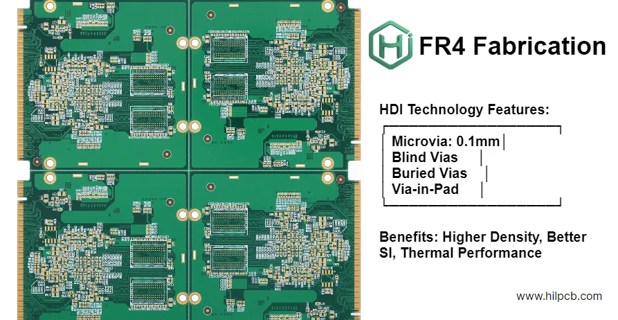
If your design requires higher layer counts, or blind/buried vias, check out our multilayer PCB and HDI PCB capabilities.
FR4 Fabrication Capabilities
We provide full-range FR4 PCB fabrication services, supporting both standard and customized specifications:
| Capability | Standard Range | Advanced Options |
|---|---|---|
| Layers | 2–16 layers | Up to 30 layers |
| Board Thickness | 0.8 mm – 3.0 mm | Custom thickness available |
| Copper Weight | 1 oz | 2–4 oz (heavy copper) |
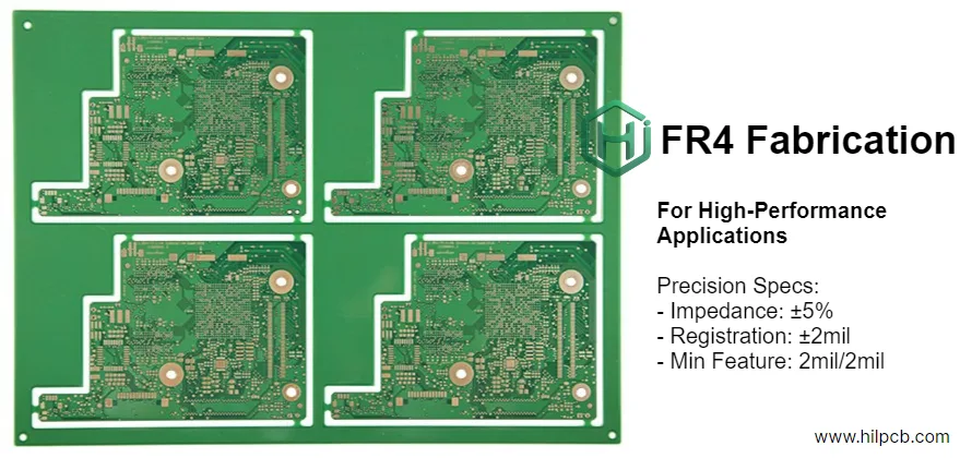
| Min. Line / Space | 3 mil / 3 mil | 2 mil / 2 mil |
| Min. Hole Size | 0.2 mm (mechanical) | 0.1 mm (laser microvia) |
| Surface Finish | ENIG, HASL, Immersion Silver, Immersion Tin | Custom finishes |
| Impedance Control | ±10% standard | ±5% precision |
| Solder Mask | Green, Black, White, Blue, Red | Custom colors |
We follow strict IPC standards to ensure consistent quality across all stages of FR4 PCB manufacturing. Each batch goes through automated optical inspection (AOI), electrical testing, and impedance verification. For more on our fabrication process, visit PCB manufacturing.
Choosing the Right FR4 Material for High-Quality PCB Fabrication
Selecting the proper FR4 material is the most critical step in ensuring your PCB performs reliably while staying within budget. Not all FR4 laminates are the same — small differences in glass transition temperature (Tg), dielectric constant (Dk), and loss factor (Df) can significantly impact signal integrity, soldering stability, and overall reliability.
1. Standard vs. High-Tg FR4
Standard FR4 (Tg 130–140°C) works well for simple consumer products and low-heat environments. If your design experiences lead-free soldering, continuous high current, or extended thermal cycling, you should select High-Tg FR4 (Tg ≥ 170°C).** High-Tg materials offer:
- Better heat resistance during reflow
- Reduced risk of delamination and warpage
- Improved dimensional stability for multilayer and HDI PCB designs
2. FR4 Thickness and Stack-Up Optimization
The board thickness directly affects impedance and mechanical stability.
- Typical thickness: 1.6 mm
- Thin FR4 (≤1.0 mm): Ideal for compact wearables or modules
- Thick FR4 (≥2.0 mm): Best for power boards and mechanical rigidity
Our engineering team can help you customize your layer stack-up to balance signal routing space, copper thickness, and impedance control. You can also explore our multilayer PCB options for high-speed or power-dense designs.
3. Copper Weight and Current Capacity
When planning FR4 fabrication, choosing the correct copper thickness is crucial for thermal management and power delivery:
- 1 oz copper: Standard for signal and low-current layers
- 2 oz copper: Enhanced current-carrying capacity
- 3–4 oz (heavy copper): Suitable for power or automotive applications
Heavy copper designs must also adjust minimum trace width and spacing to avoid over-etching and maintain manufacturability.
4. Balancing Cost vs. Performance
Cost optimization in FR4 PCB manufacturing is not only about choosing the cheapest material. The right supplier can help you find the sweet spot between cost, performance, and reliability by:
- Selecting materials available in local inventory to shorten lead time
- Designing standard panel sizes for higher fabrication yield
- Simplifying via structures unless high-density routing is required
- Choosing cost-effective finishes like Immersion Tin or HASL when ENIG is not mandatory
Our team specializes in engineering-driven cost reduction — without compromising board quality or consistency.
5. Avoiding Common Mistakes When Ordering FR4 PCBs
Before you finalize your order, check these key details to prevent production issues:
- Missing or inconsistent impedance targets in design files
- Incorrect copper thickness specifications between layers
- Mismatch between surface finish and assembly temperature profile
- No allowance for panelization and tooling holes
We review every file before production as part of our free DFM analysis, ensuring your FR4 PCB will be manufacturable and assembly-ready on the first run.
Looking for the most suitable FR4 material for your design? Get a free engineering review + quotation from our team within 24 hours → Request a Quote
FR4 PCB Assembly Services (Turnkey PCBA)
We not only fabricate PCBs but also provide complete PCB assembly solutions. Our one-stop PCB + PCBA service includes:
- SMT & Through-hole assembly
- BGA, QFN, and fine-pitch component mounting
- X-ray inspection and functional testing
- Component sourcing from authorized distributors
- Fast prototype and small-batch turnaround
By combining FR4 fabrication and assembly under one roof, we minimize communication gaps, reduce lead time, and ensure design consistency.
How to Optimize Cost and Lead Time for FR4 Fabrication
- Simplify layer count if possible; fewer layers reduce lamination cost.
- Choose standard board thickness (1.6 mm FR4) to use stocked materials.
- Keep impedance tolerance within ±10% unless strict requirements exist.
- Select economical surface finishes such as Immersion Tin or HASL when applicable.
- Panelize boards efficiently to improve production yield and SMT throughput.
Typical production time for FR4 boards:
- Prototype: 5–7 days
- HDI or complex multilayer: 10–12 days
- Volume orders: 12–15 days
Quality Assurance and Certifications
All our FR4 PCBs are manufactured in compliance with:
- IPC-6012 / IPC-A-600 (Class 2 & Class 3)
- ISO 9001, IATF 16949, RoHS and REACH standards
- 100% electrical testing and impedance verification
- Optional cross-section and micro-cut analysis for critical builds
With our integrated PCB manufacturing and assembly workflow, you can expect consistent quality and complete traceability from raw material to finished product.
Why Choose Us for FR4 Fabrication and Assembly
- ✅ One-stop solution: FR4 PCB fabrication + component assembly
- ✅ Fast turnaround: Rapid prototyping to mass production
- ✅ Engineering support: DFM/DFT & impedance consultation
- ✅ Certified quality: IPC, ISO, and IATF standards
- ✅ Global delivery: On-time shipping worldwide
We have years of experience supporting clients from startups to OEM manufacturers, providing stable FR4 boards that meet both electrical and mechanical expectations.
Get a Fast Quote for Your FR4 Fabrication Project
Ready to start your next project? Upload your Gerber files and BOM to get a detailed quotation and engineering review within 24 hours.
👉 Request a Quote Explore our full capabilities: PCB manufacturing | multilayer PCB | HDI PCB
Frequently Asked Questions
What's the difference between Class 2 and Class 3 fabrication?
Class 3 requires tighter tolerances, additional inspection points, and stricter acceptance criteria than Class 2. Class 3 is for high-reliability applications where extended life and continued performance is critical (medical, aerospace). Class 2 is for general electronics. Class 3 typically adds 20-30% to cost.
Can you mix different copper weights on the same PCB?
Yes, mixed copper construction is common. Typically outer layers use 1oz copper for fine features while inner power planes use 2-3oz for current carrying. This requires careful process control during fabrication but provides optimal performance.
How accurate can you hold impedance tolerance?
Standard impedance tolerance is ±10%. We routinely achieve ±7-8% on production runs. For critical applications, we can target ±5% with controlled-Dk materials and tighter process control. Tighter than ±5% becomes increasingly difficult and expensive with FR4 due to inherent material variability.
What lead times should I expect for precision FR4 fabrication?
Prototype quantities: 5-7 days for standard complexity, 10-12 days for HDI or complex multilayer. Production: 12-15 days typical. Complex designs with many layers or special processes may require additional time for process development.
Do you provide failure analysis for reliability issues?
Yes, we maintain microsection analysis capability and can investigate field failures. We provide detailed photo documentation, cross-section analysis, and root cause recommendations. Understanding failure modes helps improve both design and manufacturing processes.