When LED arrays fail prematurely, automotive inverters overheat, or power supplies underperform, the root cause is often inadequate thermal management. Traditional FR4 boards, with thermal conductivity of just 0.3 W/mK, cannot handle the heat generated by high-power electronics, causing components to exceed safe operating temperatures and reducing lifespan and reliability.
Metal core PCB (MCPCB) technology addresses this challenge by replacing insulating FR4 with a thermally conductive metal substrate, typically aluminum, which transfers heat 8–10 times faster. At HILPCB, we manufacture metal core PCBs optimized for thermal performance. Our PCB manufacturing process uses advanced materials, precision fabrication, and rigorous testing to ensure boards maintain stable temperatures under sustained high-power loads.
Understanding Metal Core PCB Construction
A metal core PCB consists of three functional layers designed to manage both electrical signals and thermal energy:
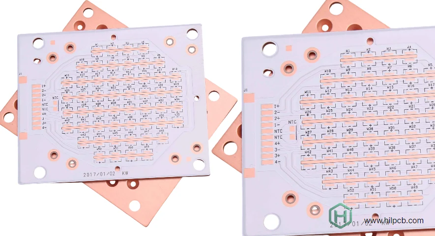
Copper Circuit Layer – Standard 1–10 oz copper provides electrical connectivity. For high-current applications exceeding 50A, heavy copper PCB technology integrates 3–10 oz copper for enhanced current capacity and thermal spreading.
Dielectric Layer – A thin (50–200 µm) thermally conductive but electrically insulating layer bonds copper to metal. This critical layer uses ceramic-filled polymer composites achieving 1–5 W/mK thermal conductivity—dramatically higher than FR4's 0.3 W/mK.
Metal Base – Aluminum alloy (1.0–3.0 mm thick) serves as heat spreader, mechanical support, and EMI shield. With thermal conductivity of 200 W/mK, aluminum substrate rapidly distributes heat across the board surface.
Unlike FR4 where heat struggles through low-conductivity substrate, aluminum PCB transfers heat laterally before dissipating to ambient air or heatsinks. This reduces component junction temperatures by 30–50°C compared to traditional designs.
Types of Metal Core PCB
Single-Layer Aluminum Core PCB
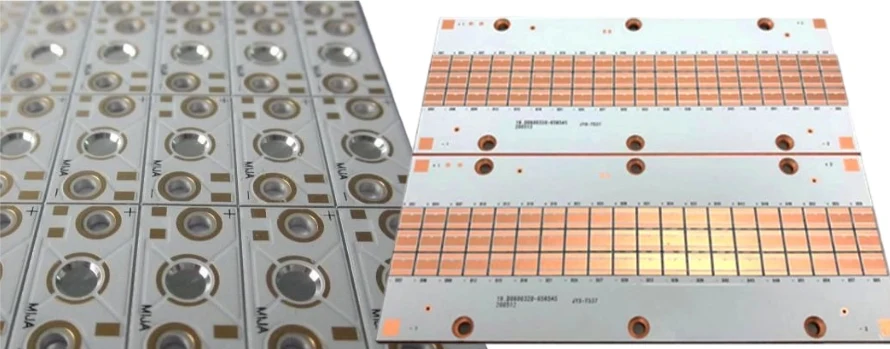
The most common configuration places components on one side with metal base below. Ideal for LED lighting, motor drives, and power supplies where circuit complexity is moderate but thermal demands are high.
Double-Sided Aluminum Circuit Board
Advanced designs route copper on both sides of the aluminum substrate using specialized via techniques. Provides higher circuit density while maintaining excellent thermal performance. Common in automotive electronics and high-power RF amplifiers.
Hybrid Construction
Some applications combine standard FR4 multilayer sections with aluminum base regions. Signal processing uses traditional stackups while power stages benefit from metal substrate contact. Aluminum clad PCB hybrid designs suit complex mixed-signal applications.
Copper Core for Extreme Performance
Where aluminum's 200 W/mK proves insufficient, copper substrates (400 W/mK) provide superior thermal conductivity. Higher cost justifies use in aerospace, military RF, and concentrated photovoltaic applications.
Thermal Performance Advantages
The thermal superiority of aluminum base PCB becomes clear in direct comparison:
| Parameter | FR4 PCB | Aluminum PCB |
|---|---|---|
| Thermal Conductivity | 0.3 W/mK | 1–5 W/mK (dielectric) + 200 W/mK (Al) |
| Junction Temp Rise | +40–60°C | +10–25°C |
| Component Lifespan | Baseline | 2–5× longer |
| Dimensional Stability | Moderate | Excellent |
| EMI Shielding | Requires layers | Inherent |
Research demonstrates that reducing operating temperature by 10°C can double LED lifespan from 25,000 to 50,000 hours. For power semiconductors, every 10°C reduction improves reliability by approximately 50% according to Arrhenius models.
Design Considerations for Optimal Performance
Thermal Via Strategy
Aluminum circuit board designs require strategic thermal via placement beneath high-power components. Typical specifications: 0.3–0.5 mm diameter vias with 1 oz copper plating, spaced 0.8–1.2 mm apart in arrays. Hexagonal patterns maximize coverage for circular LED footprints.
Copper Weight Selection
Standard 1–2 oz copper suits signal traces. Power distribution requires 3–6 oz copper to minimize resistive losses. For extreme applications exceeding 50A, integration with heavy copper PCB technology using 8–10 oz copper becomes necessary.
Dielectric Thickness Trade-offs
Thinner dielectrics (50–75 µm) minimize thermal resistance but increase electrical stress. Thicker layers (150–200 µm) improve voltage isolation but sacrifice thermal performance. Material selection must balance thermal conductivity, breakdown voltage, and manufacturing cost.
CTE Matching
Aluminum's coefficient of thermal expansion (23 ppm/°C) differs from copper (17 ppm/°C) and dielectrics. Thermal cycling induces mechanical stress at interfaces. Proper material selection and design practices prevent delamination during temperature excursions from -40°C to +125°C.
Metal Core PCB Key Applications
- LED Lighting Systems
- Automotive Electronics
- Power Electronics
- RF and Microwave Circuits
- Street Lighting
- Automotive Headlamps
- Architectural Lighting
- Engine Control Units (ECUs)
- Transmission Controllers
- Electric Vehicle (EV) Inverters
- Battery Management Systems (BMS)
- Switch-Mode Power Supplies (SMPS)
- Motor Drives
- Solar Inverters
- Wide-Bandgap Semiconductors (SiC, GaN)
- Power Amplifiers
- Low-Impedance Grounding Applications
Manufacturing Process at HILPCB
Our metal core PCB manufacturing facility implements advanced process control:
Material Preparation – Aluminum substrate undergoes surface treatment (anodizing or conversion coating) to enhance adhesion and prevent oxidation.
Dielectric Lamination – Thermally conductive prepreg pressed onto aluminum under controlled temperature and pressure. Process monitoring ensures void-free bonding and consistent thickness.
Circuit Formation – Standard photolithographic processes define patterns. Controlled etching maintains precise trace geometry critical for electrical performance.
Drilling and Routing – CNC operations use specialized tooling for metal substrates, preventing burr formation while maintaining dimensional accuracy.
Testing and Verification – Electrical testing, thermal imaging, and dimensional inspection ensure every board meets specifications. Full documentation supports customer qualification requirements.
Our PCB manufacturing facility holds ISO 9001, UL, IPC-6012 Class 2/3, and IATF 16949 certifications for automotive applications.
Why Choose HILPCB for Metal Core PCB
Advanced Material Engineering – We source optimized dielectric systems from leading suppliers, ensuring the right balance of thermal performance, voltage isolation, and cost for your application.
Thermal Design Support – Our engineering team performs finite element analysis to predict junction temperatures and validate design effectiveness before manufacturing.
Comprehensive Capabilities – In-house fabrication spans single to double-sided constructions, hybrid FR4/aluminum designs, and heavy copper integration up to 10 oz.
Fast Turnaround – Standard lead time is 5–7 days for prototypes (1–50 boards) and 10–15 days for production volumes. Expedited services available for urgent projects.
Global Quality Standards – Complete material traceability with thermal conductivity data, dielectric strength reports, and composition certifications. All documentation supports regulatory compliance and customer qualification processes.
Whether you're designing LED lighting, automotive power modules, or RF amplifiers, HILPCB delivers metal core PCB solutions engineered for thermal performance and manufacturing reliability.
Frequently Asked Questions
Q1: What is the difference between MCPCB and aluminum PCB? MCPCB is a general term for any PCB using a metal substrate for thermal management. Aluminum PCB specifically refers to boards using aluminum as the base material—the most common type due to aluminum's excellent thermal conductivity (200 W/mK) and cost-effectiveness.
Q2: Can metal core PCBs be multilayer? Yes, though most designs are single or double-sided for optimal thermal performance. Multilayer hybrid constructions combine FR4 sections with aluminum base regions for applications requiring both complex routing and localized thermal management.
Q3: What is the typical aluminum substrate thickness? Standard thickness ranges from 1.0 to 3.0 mm. Thicker substrates (2.0–3.0 mm) provide better mechanical rigidity and heat spreading. Thinner substrates (1.0–1.5 mm) reduce weight and cost for less demanding applications.
Q4: Are aluminum PCBs compatible with standard SMT assembly? Yes, fully compatible with automated SMT processes. The higher thermal mass requires slight reflow profile adjustments—typically 5–10°C higher peak temperature or 10–20 seconds longer time above liquidus for complete solder joint formation.
Q5: How much temperature reduction can I expect vs FR4? Typical aluminum PCB designs reduce component junction temperatures by 30–50°C compared to equivalent FR4 implementations for the same power dissipation and board area. Actual results depend on component power density, thermal via design, and ambient conditions.