Modern radar systems demand exceptional precision, stability, and performance from their circuit boards. Whether for automotive collision avoidance, military surveillance, weather monitoring, or aerospace navigation, Radar PCBs must operate flawlessly across extreme frequencies—often ranging from 24 GHz to 300 GHz—while maintaining signal integrity in harsh environmental conditions.
Our advanced Radar PCB manufacturing capabilities combine specialized materials, precision engineering, and rigorous testing protocols to deliver boards that meet the exacting standards of defense contractors, automotive OEMs, and aerospace manufacturers worldwide.
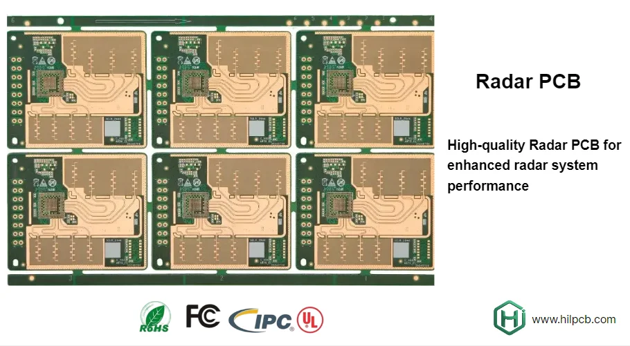
What is Radar PCB and How Does It Support Radar Systems?
A Radar PCB serves as the foundational circuit platform for radar systems, managing the transmission and reception of electromagnetic waves used to detect objects, measure distances, and determine velocities. Unlike conventional circuit boards, Radar PCBs must handle millimeter-wave frequencies with minimal signal loss, maintain precise impedance control, and operate reliably across temperature extremes ranging from -55°C to +125°C.
Core Functions in Radar Systems:
- Signal Generation and Modulation – Creating precise frequency-modulated continuous wave (FMCW) or pulsed radar signals
- Power Amplification – Boosting transmitted signals to required power levels without introducing distortion
- Low-Noise Reception – Capturing weak reflected signals with minimal interference from the board itself
- Signal Processing – Converting analog returns into digital data for target identification and tracking
- Timing Synchronization – Maintaining nanosecond-level precision for accurate range measurements
Application-Specific Requirements:
Different radar applications demand tailored PCB solutions. Automotive radar systems (24 GHz, 77 GHz, 79 GHz) require compact designs with excellent thermal management for in-vehicle electronics. Military and aerospace radar operates at higher frequencies (X-band, Ku-band, Ka-band) and needs radiation-hardened materials for space applications or ruggedized construction for battlefield conditions. Weather radar systems prioritize long-term stability and resistance to moisture exposure.
Our high-frequency PCB manufacturing process addresses these diverse requirements through material selection, stack-up optimization, and manufacturing precision that exceed standard commercial board specifications.

How to Optimize Signal Integrity for Radar Circuits
Signal integrity is a crucial factor in Radar PCB design. At high frequencies, even slight imperfections in the PCB can cause reflections, insertion loss, and phase distortion, all of which can degrade radar performance.
Controlled Impedance Design: To maintain consistent 50-ohm impedance, we ensure precise control over trace geometry, dielectric thickness, and copper weight. Using electromagnetic field simulation, we achieve ±5% impedance tolerance across the entire frequency range.
Minimizing Dielectric Loss: We select low-loss materials with a dissipation factor below 0.002 at 10 GHz, ensuring minimal signal attenuation even at high radar frequencies like 77 GHz. This ensures efficient power transmission and optimal receive sensitivity.
Via Design and Grounding Strategy: Ground vias are essential for maintaining return current paths and RF shielding. We implement grounded coplanar waveguide (GCPW) structures and use HDI PCBs with blind/buried vias to enable compact designs while maintaining signal integrity.
Surface Finish Selection: For radar applications, we recommend finishes like immersion silver or ENEPIG for minimal loss and superior corrosion resistance, especially for military and aerospace applications.
Layout Best Practices: We review trace routing to avoid mismatches and ensure proper isolation between sensitive receiver circuits and high-power transmit paths. This reduces design issues before fabrication, saving time and improving first-pass yield.
Why Choose RO4000 for Radar PCBs?
Rogers RO4000 series laminates are the industry standard for high-frequency Radar PCBs, offering a balance of electrical performance, thermal stability, and manufacturability.
Material Advantages: RO4000 laminates have a dielectric constant (Dk) of 3.38 to 3.48 at 10 GHz and a dissipation factor of 0.0027, ensuring low insertion loss and high sensitivity. RO4000 is compatible with standard FR4 PCB fabrication equipment, reducing costs and lead times.
Thermal Performance: RO4000 maintains stable performance over a temperature range of -50°C to +280°C, with a thermal conductivity of 0.62 W/mK for effective heat dissipation, ensuring reliable radar performance across extreme conditions.
Design Flexibility: With multiple dielectric thicknesses and copper weights, RO4000 offers flexibility for various radar frequencies and power levels. For example, automotive radar at 77 GHz typically uses thinner dielectrics (5-10 mil), while thicker cores provide mechanical strength for lower-frequency radar.
**Proven Reliability: ** RO4000 meets IPC-4103 standards and has been validated through accelerated aging, thermal cycling, and humidity tests. Its reliability has been proven in automotive, aerospace, and military applications, reducing qualification risks.
Our expertise with Rogers PCB materials includes stack-up design, impedance modeling, and fabrication process optimization, ensuring maximum performance in your radar applications.
Validating Radar PCB Performance Through Testing
For radar systems, it’s essential that PCBs meet both electrical specifications and reliability standards. Proper testing ensures the performance of radar systems in high-frequency environments, where even small imperfections can significantly impact accuracy and reliability.
Key elements of our testing process for Radar PCBs include:
- Electrical Characterization to verify insertion loss, return loss, and impedance using vector network analyzers (VNA)
- Antenna Port Validation to ensure optimal impedance matching and phase accuracy for antenna feeds in phased array systems
- High-Power Testing at 1.5× rated power to assess power handling, thermal stress, and detect potential hotspots using thermal imaging
- Environmental Qualification to simulate real-world conditions through thermal shock cycling, high-temperature storage, and moisture resistance testing
- Reliability Testing with MIL-STD-883 protocols to evaluate mechanical shock, vibration, and radiation tolerance for military and aerospace applications
By conducting these tests, we ensure Radar PCBs meet stringent performance standards, maintain long-term reliability, and perform effectively even in the harshest environments. This helps ensure the successful operation of radar systems in critical applications such as military surveillance, automotive radar, and satellite communication.
How to Quickly Get a Quote for Radar PCBs
Obtaining an accurate quote for Radar PCB manufacturing requires clear communication of technical requirements and application context.
Essential Information for Quoting:
To provide a comprehensive quote, we need the following details:
- Frequency Range – Operating band determines material selection and fabrication tolerances (e.g., 77 GHz automotive, Ka-band military)
- Layer Count and Stack-up – Specify substrate materials, dielectric thicknesses, and copper weights for each layer
- Board Dimensions – Outline size, panel utilization, and whether boards will be supplied as singles or arrays
- Impedance Requirements – Controlled impedance traces with target values and tolerances (typically ±5 ohms for 50-ohm lines)
- Surface Finish – ENIG, immersion silver, or ENEPIG based on application requirements
- Quantity and Lead Time – Production volume and required delivery date affect pricing and manufacturing approach
Expedited Quoting Process:
For urgent projects, our online quoting system provides preliminary pricing within 2 hours for standard radar configurations using RO4000 materials. Simply upload your Gerber files, specify material requirements, and indicate any special testing needs. Our engineering team reviews each quote request to identify potential design issues that could affect manufacturability or performance, providing feedback along with pricing.
Design for Manufacturability (DFM) Review:
Complex radar boards benefit from early DFM consultation. We offer complimentary design reviews for projects above minimum order values, identifying opportunities to optimize layer stack-up, improve impedance control, or reduce fabrication costs without compromising performance. This collaborative approach often reduces prototype costs by 15-30% while improving first-pass yield.
Prototype to Production Pathway:
Our flexible manufacturing process supports projects from initial prototypes through high-volume production. Prototype orders (5-25 pieces) use the same materials and processes as production builds, ensuring that prototype test results accurately predict production performance. As volumes increase, we optimize panel layouts and implement automated inspection to reduce unit costs while maintaining the precision required for radar applications.
Global Delivery and Support:
We ship Radar PCBs worldwide with full traceability documentation including certificates of conformance, test data, and quality inspection reports. For international defense projects, we provide export compliance support and can manufacture boards in facilities certified to ITAR, ISO 9001, AS9100, and IPC-6012 Class 3/A standards.
To receive your Radar PCB quote, visit our online portal or contact our applications engineering team directly. We're committed to delivering the precision, performance, and reliability your radar systems demand.
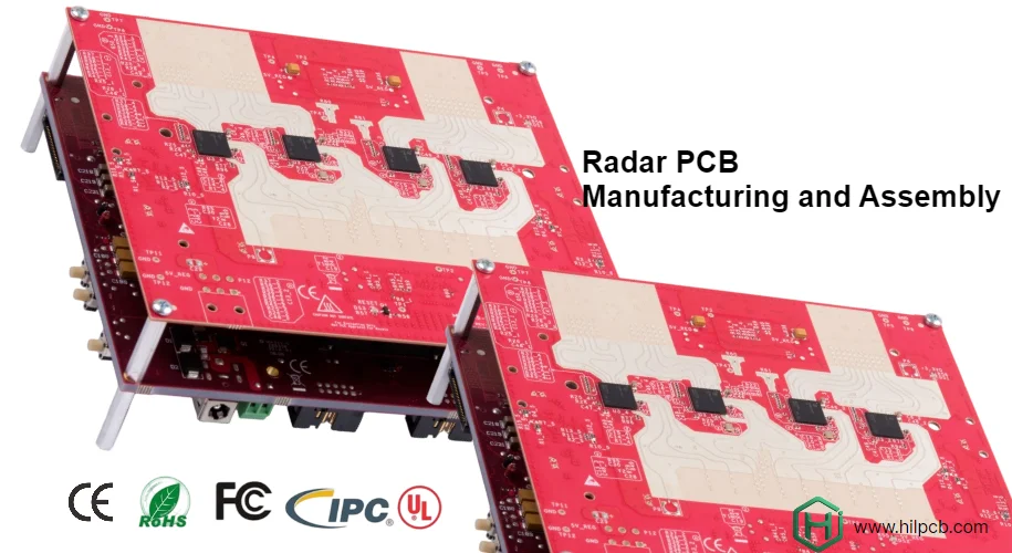
End-to-End Solutions for Radar PCB Success
Successful radar system development extends beyond PCB fabrication to include assembly, testing, and integration support.
Our comprehensive services include:
- Advanced PCB fabrication using Rogers RO4000, RO3000, and other high-frequency laminates
- Precision SMT assembly with placement accuracy to ±25 microns for fine-pitch RF components
- RF testing and characterization up to 110 GHz frequencies
- Thermal management solutions including metal core PCB for high-power radar applications
- Design consultation and signal integrity analysis using electromagnetic simulation
- Complete turnkey assembly from bare boards through programmed, tested radar modules
By partnering with a single manufacturer for fabrication, assembly, and test, you reduce supply chain complexity, accelerate development cycles, and ensure consistent quality from prototype through volume production. Our radar PCB expertise, combined with comprehensive manufacturing capabilities, makes us the ideal partner for your next-generation radar system.