Rigid flex circuit board design looks deceptively simple until you encounter your first field failure. A medical device company learned this the hard way when 2,000 shipped units started failing after six months—boards cracking at rigid-flex transitions under normal use. The root cause? Design decisions made without understanding how rigid and flexible materials behave together under stress.
Successful rigid flex circuit board design requires balancing mechanical, electrical, and manufacturing considerations that don't exist in standard PCB design. At HILPCB, we've helped hundreds of engineers navigate these challenges, from HDI PCB integration to managing flex cycles in dynamic applications.
Understanding Rigid Flex Circuit Board Fundamentals
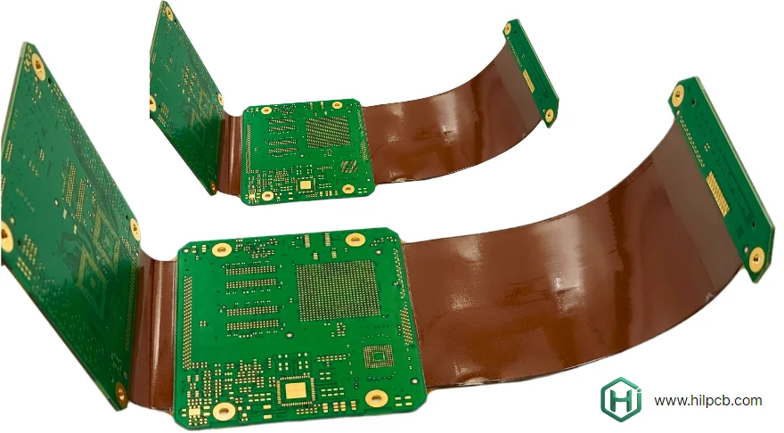
Before diving into design rules, understanding how rigid flex circuit boards actually function prevents most common mistakes. Unlike standard PCBs where boards remain flat and stationary, rigid flex designs must accommodate movement, bending, and mechanical stress.
The transition zone between rigid and flexible sections creates the highest stress concentration points in your design. When a board bends, these transitions act like mechanical hinges—but they're made of copper and polyimide, not steel. A consumer electronics manufacturer discovered this when their fitness tracker design failed after 3,000 flex cycles. The rigid section extended too close to the flex area, creating a stress riser that caused copper fractures.
Material Behavior Differences
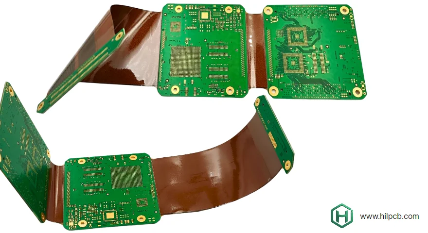
Rigid and flexible sections use fundamentally different materials with distinct properties. Standard FR4 PCB materials work well for rigid sections but cannot flex. Polyimide-based flexible circuits handle bending but cost more and require special processing.
The key is understanding where each material type belongs in your design. Rigid sections provide component mounting areas and structural support. Flexible sections enable movement, folding, or packaging in 3D spaces. The transition zones connect these areas while managing mechanical stress.
Critical Design Rules for Transition Zones
Transition zones make or break rigid flex circuit board reliability. These areas where rigid sections meet flexible circuits require careful attention to geometry, materials, and stress management.
Minimum Transition Length
Never extend rigid areas all the way to flex sections. Leave minimum 3mm transition zone using stiffeners or reduced stack-ups before entering fully flexible areas. This graduated transition distributes bending stress over larger area rather than concentrating it at a single point.
An IoT device manufacturer ignored this rule to save 2mm of board space. Their design experienced 40% field failure rate within first year. Redesigning with proper transition zones eliminated failures but cost $80,000 in recalls and retooling.
Copper Management in Flex Regions
Copper thickness and routing patterns dramatically affect flex life. Heavy copper traces create stiff areas that resist bending—exactly what you don't want in flexible sections. We recommend:
- Maximum 1 oz (35μm) copper in dynamic flex areas
- 0.5 oz (18μm) copper for applications requiring 10,000+ flex cycles
- Route traces perpendicular to bend lines when possible
- Avoid sharp 90° corners—use curved traces with minimum radius 3x trace width
- Stagger vias away from high-stress areas
Layer Stack-Up Considerations
Every additional layer in flexible sections reduces flex life. A 2-layer flex PCB can achieve 100,000+ flex cycles. Add two more layers and you're down to 10,000 cycles under same conditions. Plan your rigid flex circuit board stack-up based on actual flex requirements:
- Static flex (one-time installation bending): 4-6 layers acceptable
- Occasional flex (<100 cycles): 2-4 layers recommended
- Dynamic flex (>1,000 cycles): 1-2 layers maximum in flex regions
Material Selection Strategy
Choosing the right materials for rigid flex circuit board construction determines manufacturing success and long-term reliability. Unlike standard PCBs where FR4 handles almost everything, rigid flex designs require matching materials to specific application requirements.
Polyimide Film Options
Two polyimide construction types dominate rigid flex circuit boards: adhesive-based and adhesiveless. The choice significantly impacts reliability and cost.
Adhesive-based construction uses acrylic or epoxy adhesive to bond copper to polyimide film. This method costs less and works well for static or low-cycle applications. However, adhesive can fail under repeated flexing as the adhesive fatigues faster than copper or polyimide. Maximum reliable flex cycles: 10,000-50,000 depending on bend radius and stress levels.
Adhesiveless construction bonds copper directly to polyimide through chemical processes. This eliminates adhesive failure mode and supports 100,000+ flex cycles in properly designed circuits. Cost runs 30-50% higher than adhesive-based but proves essential for dynamic flexing applications.
Coverlay vs Solder Mask
Flexible sections require protection but traditional solder mask proves too rigid for flex areas. Coverlay—a layer of polyimide with adhesive—provides flexible protection that moves with the circuit.
For static flex areas or where bending occurs outside the circuit pattern, solder mask may work. But for any dynamic flexing or tight bend radii, coverlay is mandatory. A wearable device design originally specified solder mask to save cost. During qualification testing, the mask cracked after 500 flex cycles, exposing copper traces to corrosion.
Stiffener Materials
Stiffeners support flexible sections during assembly and provide attachment points for connectors. Material choices include:
- FR4: Most common, works with standard SMT assembly processes
- Polyimide: Better CTE match to flex circuits, recommended for thermal cycling
- Stainless steel: Provides maximum support for heavy connectors
- Aluminum: Offers electromagnetic shielding plus mechanical support
Designing for Manufacturability
Even perfect electrical design fails if manufacturing cannot produce it reliably. Rigid flex circuit board manufacturing combines multiple specialized processes—each with specific design requirements for optimal yield.
Registration and Tolerance Management
Rigid flex manufacturing requires precise alignment between rigid and flexible sections during lamination. Standard PCB tolerances don't apply—you need tighter specifications.
Specify minimum 0.5mm clearance between edges of rigid sections and flexible circuit patterns. This accommodates lamination misregistration while preventing rigid areas from extending over flex circuits. For high-frequency PCB applications requiring controlled impedance, increase clearances to 0.75mm minimum.
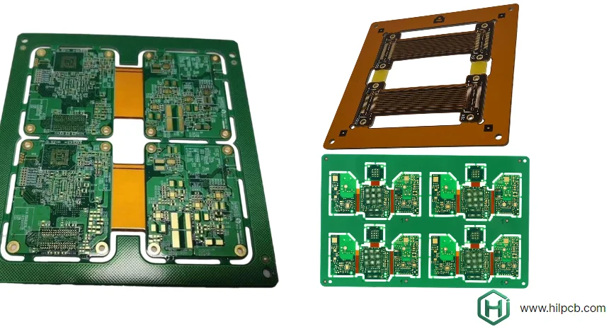
Panelization Strategy
Unlike standard PCBs where panelization is straightforward, rigid flex boards require careful planning. The flexible sections can't support typical breakaway tabs. Instead, use:
- Rigid area support points for panel attachment
- Perforated lines for flex section separation
- Strategic stiffener placement to support panel handling
- Clear documentation showing assembly orientation
Preview your design using our online PCB viewer tool before submission, though complete design files for quotes must go through our quote request page for proper engineering review.
Testing and Qualification Requirements
Designing reliable rigid flex circuit boards requires validation beyond standard electrical testing. Mechanical performance under real-world conditions determines product success or failure in the field.
Flex Cycle Testing
Specify and verify minimum flex cycles your application requires. Testing should replicate actual use conditions including:
- Bend radius matching product constraints
- Flexing speed representative of actual use
- Environmental conditions (temperature, humidity)
- Continuous cycling to 2-3x expected life minimum
A medical device manufacturer specified 50,000 flex cycles for their handheld diagnostic tool. Testing to exactly 50,000 cycles showed passing results, but field units started failing around 40,000 cycles due to variations in assembly and use conditions. Testing to 150,000 cycles (3x specification) revealed the actual design margin and enabled optimization before production.
Environmental Testing
Rigid flex circuit boards often operate in challenging environments. Comprehensive testing should include:
- Temperature cycling across expected operating range
- Humidity exposure for outdoor or medical applications
- Vibration testing for automotive or aerospace use
- Chemical resistance if exposed to cleaning agents or bodily fluids
Our turnkey assembly service includes application-specific environmental testing, ensuring your product meets real-world requirements before production scaling.
Common Design Mistakes to Avoid
Insufficient Bend Radius
The single most common rigid flex failure: specifying bend radius too tight for the stack-up. Minimum bend radius depends on total material thickness—6x to 10x thickness for static bending, 10x to 20x for dynamic flexing. Ignoring this rule guarantees copper cracking and circuit failure.
Components Too Close to Flex Areas
Placing components within 3mm of flex boundaries creates stress concentration during bending. The component acts as a rigid stress riser, magnifying forces at solder joints and traces. Move components back or add stiffener support.
Inadequate Strain Relief
Connectors and cables experience pulling forces during use. Without proper strain relief design, these forces transfer directly to solder joints and traces. Add mechanical anchoring and flex loops to absorb movement.
Frequently Asked Questions - Rigid Flex Circuit Board Design
Q1: What software works best for rigid flex circuit board design?
Most professional PCB design tools support rigid flex: Altium Designer, Cadence Allegro, Mentor Graphics, and KiCAD. The key is understanding the design rules, not the specific software. We work with designs from any professional CAD system. Our engineering team provides design rule checks regardless of which tool you use.
Q2: How many flex cycles can rigid flex circuit boards handle?
Flex cycle life depends on design parameters: 1-layer flex with 0.5oz copper: 100,000+ cycles. 2-layer flex with 1oz copper: 50,000+ cycles. 4-layer flex: 10,000-20,000 cycles. Adhesiveless construction vs adhesive-based: 2-5x improvement. Bend radius larger vs tighter: 5-10x life difference. Proper design easily achieves most application requirements.
Q3: Can I convert existing PCB design to rigid flex?
Often yes, but requires engineering analysis. We review your current design, identify rigid vs flexible areas, optimize layer stack-up for each region, design proper transition zones, and recommend material specifications. Submit your existing design through quote request page for conversion feasibility assessment and pricing.
Q4: What's the cost difference between rigid flex and standard PCB plus flex cable?
Rigid flex typically costs more per board ($15-45 vs $8-20 for separate rigid + flex cable). However, system level analysis often shows savings: Eliminated connectors, reduced assembly time, improved reliability, smaller overall package size. ROI usually positive at production volumes above 1,000 units annually.
Q5: How do I specify rigid flex circuit board requirements to manufacturer?
Provide complete documentation: Gerber or ODB++ files with clear layer identification, IPC-2223 sectional view showing stack-up, bend radius and flex cycle requirements, environmental operating conditions, assembly and testing requirements. Upload through our quote request page for complete engineering review and DFM analysis.