Material selection determines whether your rigid flex substrate survives 1,000 flex cycles or 100,000. A fitness tracker manufacturer learned this expensive lesson when their product started failing after 6 months. The issue wasn't design or manufacturing quality—it was material choice. They specified adhesive-based polyimide to save $0.85 per unit, but their application required 50,000+ flex cycles. The adhesive fatigued and delaminated, causing 15% field failure rate.
Redesigning with adhesiveless polyimide eliminated failures but required recall of 12,000 units at total cost exceeding $180,000. Understanding rigid flex substrate materials before production would have prevented this disaster.
At HILPCB, we guide customers through material selection based on actual application requirements, combining FR4 PCB expertise for rigid sections with specialized flexible substrate knowledge for dynamic areas.
Polyimide Film Types and Selection
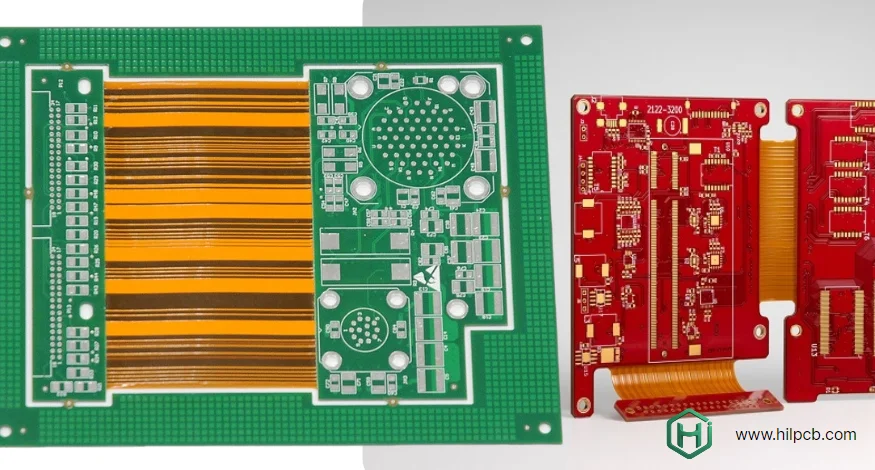
Polyimide forms the foundation of all flexible sections in rigid flex substrates. But "polyimide" isn't a single material—it encompasses multiple film types with significantly different properties and performance characteristics.
Adhesive-Based Construction
Adhesive-based polyimide uses separate adhesive layer (typically acrylic or modified epoxy) bonding copper to polyimide film. This construction method offers several advantages: lower material cost ($8-15 per square foot vs $18-30 for adhesiveless), easier processing with standard lamination equipment, and good performance for static or low-cycle applications.
However, adhesive creates a weak link in dynamic flexing applications. The adhesive layer experiences different stress and strain compared to polyimide and copper layers. Over repeated flex cycles, this differential creates fatigue in the adhesive, eventually leading to copper-to-polyimide delamination.
When to Use Adhesive-Based:
- Static flex applications (one-time installation bending)
- Low cycle count (<10,000 flex cycles)
- Cost-sensitive consumer products with moderate life requirements
- Operating temperatures below 150°C
- Applications where weight and thickness aren't critical constraints
Adhesiveless Construction
Adhesiveless polyimide bonds copper directly to polyimide through chemical processes, eliminating the adhesive layer entirely. This creates thinner, lighter substrates with superior flex life: 100,000-1,000,000 cycles possible with proper design.
The chemical bonding creates molecular-level attachment between copper and polyimide. This eliminates the weakest link found in adhesive-based constructions. A medical device manufacturer testing both materials found adhesiveless construction survived 10x more flex cycles than adhesive-based using identical copper thickness and bend radius.
When to Use Adhesiveless:
- Dynamic flexing applications (>10,000 cycles)
- Tight bend radius requirements
- High operating temperatures (>150°C)
- Weight-critical applications (aerospace, wearables)
- Medical devices requiring maximum reliability
- Applications where long-term reliability justifies higher material cost
Rigid Section Material Options
Rigid sections in rigid flex substrates require different considerations than standalone rigid PCBs. The materials must bond reliably to flexible sections while providing adequate mechanical support and electrical performance.
Standard FR4 Laminates
Standard FR4 PCB materials work well for many rigid flex applications. FR4 offers good electrical properties, proven reliability, and cost-effectiveness. For applications operating in normal temperature ranges (-40°C to +85°C) without extreme environmental exposure, FR4 provides excellent performance.
However, FR4 has limitations for demanding applications. The glass transition temperature (Tg) of standard FR4 ranges from 130-140°C. During rigid flex lamination, materials experience temperatures exceeding 180°C. Multiple lamination cycles can degrade standard FR4 properties. For complex rigid flex substrates requiring multiple lamination stages, high-Tg materials prove more reliable.
High-Tg Materials
High-Tg PCB laminates with glass transition temperatures exceeding 170°C provide superior performance for demanding rigid flex applications. These materials maintain mechanical and electrical properties through multiple high-temperature processing steps without degradation.
An automotive electronics manufacturer initially specified standard FR4 for their rigid flex substrate. During qualification testing at +125°C operating temperature, boards experienced delamination between rigid and flexible sections. The issue traced to FR4 approaching its glass transition temperature during both processing and operation. Switching to high-Tg materials eliminated the problem while adding just $1.80 per board cost.
Specialty High-Performance Materials
Applications requiring controlled impedance, low loss at high frequencies, or extreme temperature operation may need specialty materials like Rogers PCB laminates. These materials provide:
- Consistent dielectric properties across wide frequency ranges
- Low dissipation factor for high-frequency applications
- Stable electrical properties from -55°C to +150°C
- Excellent thermal conductivity for power applications
A 5G infrastructure manufacturer uses Rogers materials in rigid sections of their rigid flex antenna assemblies. The stable dielectric constant across frequency ensures consistent antenna performance, while the material's thermal properties dissipate heat from power amplifiers effectively.
Copper Considerations for Flexible Sections
Copper type and thickness dramatically affect rigid flex substrate performance, particularly in areas subject to repeated flexing. Standard electrodeposited (ED) copper used in most PCBs proves unsuitable for dynamic flex applications.
Rolled Annealed Copper
Rolled annealed (RA) copper provides superior flex life compared to electrodeposited copper. The manufacturing process creates elongated grain structure aligned with the rolling direction. During flexing, this grain structure allows copper to bend without developing micro-cracks that propagate into circuit failures.
Testing by a wearable device manufacturer compared identical rigid flex designs using ED copper vs RA copper. The RA copper version survived 85,000 flex cycles before failure, while ED copper version failed at 12,000 cycles—7x difference from copper selection alone.
Copper Thickness Selection
Thinner copper provides better flex life, but reduces current carrying capacity and increases resistance. The balance depends on your application:
- 0.5 oz (18μm): Maximum flex life for dynamic applications, suitable for signal traces
- 1 oz (35μm): Good flex life with adequate current capacity for most applications
- 2 oz (70μm): Limited flex life, used only in static flex areas or power distribution
- 3+ oz: Never use in areas requiring flexing
A medical device design originally specified 1 oz copper throughout for manufacturing simplicity. Our engineering review identified that signal traces needed only 0.5 oz copper, providing 3x flex life improvement. Power traces requiring higher current capacity stayed at 1 oz copper in supported areas. This optimization cost nothing but dramatically improved reliability.
Coverlay and Protective Materials
Flexible circuits require protection from environmental exposure and mechanical damage. Traditional solder mask used on rigid PCBs proves too rigid for flex areas—it cracks and delaminates under flexing.
Coverlay Construction
Coverlay consists of polyimide film with adhesive on one side, laminated over exposed copper traces in flexible areas. The polyimide film matches the base substrate material, ensuring compatible flexing characteristics. Coverlay adhesive must withstand flexing without fatiguing—typically acrylic or modified epoxy formulations specifically designed for dynamic applications.
Proper coverlay overlap prevents moisture ingress and provides mechanical protection. Minimum 0.5mm overlap beyond pad edges ensures reliable sealing. An industrial sensor manufacturer experienced field failures from moisture corrosion after coverlay separated from pads. The issue traced to insufficient overlap—just 0.2mm. Increasing to 0.6mm overlap eliminated failures.
Alternative Protection Methods
For static flex areas or cost-sensitive applications, flexible solder mask provides adequate protection. Flexible solder mask costs less than coverlay but tolerates only limited flexing. It works well for rigid flex substrates where bending occurs once during assembly but not during operation.
Our high thermal PCB materials combined with appropriate coverlay enable thermal management in flexible sections while maintaining flex life—critical for LED lighting and power applications where heat dissipation occurs through flexible substrates.
Stiffener Materials and Applications
Stiffeners provide mechanical support in flexible circuit areas during assembly and operation. They prevent board bending during component placement, provide attachment points for connectors, and support areas where flexing isn't desired.
FR4 Stiffeners
FR4 stiffeners represent the most common choice for rigid flex substrates. They offer good rigidity, bond well using standard adhesives, and cost-effectively support most applications. FR4 stiffeners typically use 0.2-0.4mm thickness depending on support requirements.
The main limitation of FR4 stiffeners involves coefficient of thermal expansion (CTE) mismatch with polyimide. FR4 expands/contracts about 3x more than polyimide during temperature cycling. For applications experiencing wide temperature swings, this mismatch creates stress at stiffener edges.
Polyimide Stiffeners
Polyimide stiffeners match the CTE of flexible substrate materials, eliminating thermal stress issues. This makes them ideal for: applications experiencing wide temperature cycling (-55°C to +125°C), aerospace and automotive environments, and long-term reliability requirements.
The downside: polyimide stiffeners cost 3-5x more than FR4 alternatives. A satellite manufacturer specifies polyimide stiffeners for their rigid flex substrates despite higher cost because CTE matching proves essential for surviving orbital temperature cycling over 15-year mission life.
Metal Stiffeners
Stainless steel or aluminum stiffeners provide maximum rigidity for heavy connector support or electromagnetic shielding requirements. Metal core PCB technology enables integrated thermal management when metal stiffeners also serve as heat sinks.
An IoT gateway device uses aluminum stiffeners serving triple purpose: supporting board-to-board connectors, providing EMI shielding for sensitive RF circuits, and dissipating heat from processor and power amplifiers. This integrated approach eliminated separate shielding cans and heat spreaders, saving $3.20 per unit while improving thermal and EMI performance.
Material Selection Decision Framework
Choosing optimal rigid flex substrate materials requires systematic evaluation of application requirements. Use this framework to guide material decisions:
Step 1: Define Flex Requirements
- Static flex (one-time bending): Adhesive-based polyimide acceptable
- Dynamic flex (<10,000 cycles): Adhesive-based possible with proper design
- High-cycle flex (>10,000 cycles): Adhesiveless polyimide mandatory
Step 2: Evaluate Operating Environment
- Standard temperature (-40°C to +85°C): Standard materials work
- Automotive temperature (-55°C to +125°C): High-Tg rigid sections required
- Extreme temperature (below -55°C or above +125°C): Specialty materials needed
Step 3: Assess Electrical Requirements
- Standard signal routing: FR4 rigid sections adequate
- Controlled impedance: High-Tg or Rogers materials recommended
- High-frequency (>1 GHz): Rogers or similar low-loss materials required
Step 4: Consider Mechanical Constraints
- Thickness budget: Adhesiveless construction provides thinnest option
- Weight restrictions: Polyimide stiffeners reduce weight vs FR4
- Connector support: Metal stiffeners for heavy connectors
Preview your rigid flex substrate design using our PCB viewer tool before submission. For detailed material recommendations, submit through quote request page for engineering consultation.
Frequently Asked Questions - Rigid Flex Substrate Materials
Q1: What is difference between adhesive and adhesiveless polyimide?
Adhesive-based polyimide uses separate adhesive layer bonding copper to polyimide film. Lower cost but limited flex life (<10,000 cycles typically). Adhesiveless bonds copper directly to polyimide chemically—higher cost but 10x+ flex life. Choose adhesive for static/low-cycle applications, adhesiveless for dynamic flexing or high reliability requirements.
Q2: Can I use standard FR4 in rigid sections of rigid flex substrate?
Yes, standard FR4 works well for many applications operating at normal temperatures without extreme environmental exposure. However, high-Tg FR4 or specialty laminates recommended for: automotive applications (+125°C operation), complex designs requiring multiple lamination cycles, applications requiring controlled impedance, or extreme reliability requirements.
Q3: How does copper thickness affect rigid flex substrate performance?
Thinner copper provides better flex life but reduces current capacity. 0.5 oz copper (18μm) survives 5-10x more flex cycles than 1 oz copper (35μm). Use thinnest copper adequate for your current requirements. Power traces may need 1-2 oz copper while signal traces perform better with 0.5 oz. Never use >1 oz copper in areas requiring flexing.
Q4: What stiffener material should I choose?
FR4 stiffeners work for most applications—cost effective and adequate rigidity. Choose polyimide stiffeners for: wide temperature cycling applications, aerospace/automotive environments, or maximum long-term reliability. Choose metal stiffeners for: heavy connector support, EMI shielding requirements, or thermal management needs. Material choice adds $0.50-3.00 per board depending on option.
Q5: How do I specify rigid flex substrate materials to manufacturer?
Provide complete material specifications including: polyimide type (adhesive/adhesiveless) for flexible sections, rigid section laminate (FR4, high-Tg, Rogers, etc.), copper thickness for each layer, coverlay or solder mask specifications, stiffener type and thickness, operating temperature range, and expected flex cycles. Submit design with detailed notes through quote request page for material recommendations and optimization.