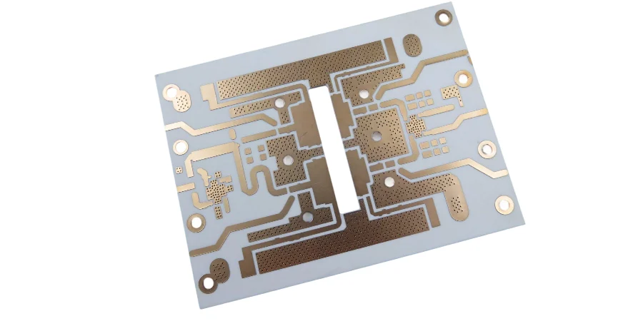
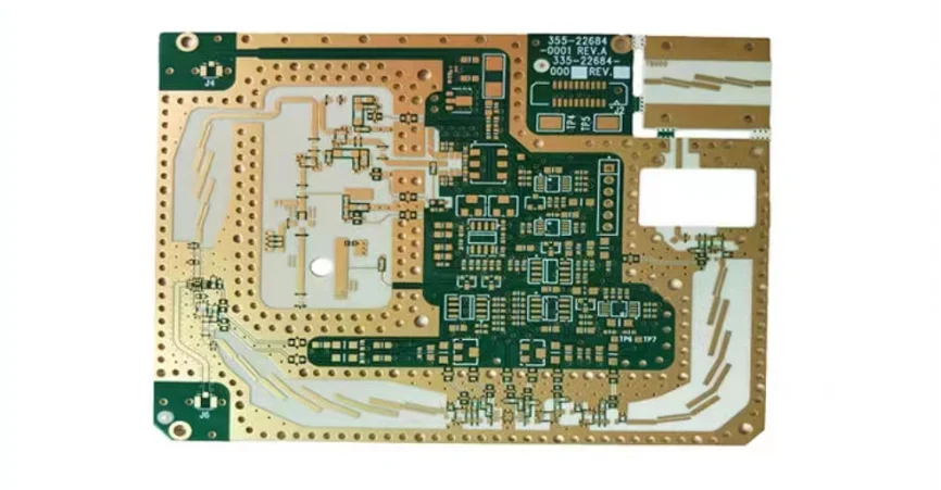
Rogers 4003C represents the pinnacle of hydrocarbon ceramic laminate technology, engineered specifically for microwave and millimeter-wave applications where dielectric consistency and low loss performance are critical. At Highleap PCB Factory, our specialized Rogers 4003C manufacturing processes address the unique challenges inherent in processing this advanced substrate material, delivering PCBs that maintain precise electrical characteristics across demanding frequency ranges.
Rogers 4003C Material Characteristics and Electrical Properties
Rogers 4003C exhibits a dielectric constant (Dk) of 3.38 ± 0.05 at 10 GHz, with exceptional frequency stability maintaining less than 2% variation from 1 MHz to 40 GHz. The dissipation factor (Df) of 0.0027 at 10 GHz ensures minimal signal attenuation in high-frequency circuits. These properties result from the material's unique glass microfiber reinforcement structure and proprietary resin formulation.
The coefficient of thermal expansion (CTE) measures 11 ppm/°C in the X-Y plane and 46 ppm/°C in the Z-axis, providing excellent dimensional stability during thermal cycling. Water absorption remains below 0.06%, significantly reducing dielectric constant drift in humid environments. The thermal conductivity of 0.71 W/m/K enables efficient heat dissipation in power amplifier applications.
Critical to Rogers 4003C performance is its glass transition temperature (Tg) of greater than 280°C, allowing for lead-free assembly processes without material degradation. The decomposition temperature exceeds 425°C, providing substantial margin for high-temperature processing requirements. These thermal properties make Rogers 4003C suitable for automotive radar applications operating from -40°C to +150°C.
Advanced Rogers 4003C PCB Fabrication Processes
Rogers 4003C processing requires specialized drilling parameters due to its ceramic-filled composition. Optimal drill speeds range from 150-250 SFM with feed rates between 3-8 IPM, depending on hole diameter and aspect ratio. Our proprietary drill bit geometry reduces ceramic particle pullout and ensures consistent hole quality throughout the drilling process.
Lamination of Rogers 4003C demands precise pressure and temperature control. We employ a staged heating profile reaching 375°C at 400 PSI, maintaining pressure for 90 minutes to achieve optimal resin flow and eliminate voids. The cooling cycle follows a controlled 2°C per minute rate to minimize internal stress and warpage. This process ensures complete cure while preventing delamination issues common with improper thermal profiles.
Chemical etching of Rogers 4003C copper requires modified etchant formulations to account for the substrate's chemical resistance. We utilize plasma desmear processes operating at 300W power with oxygen/tetrafluoromethane chemistry to remove drilling debris and activate surfaces for reliable plating adhesion. Via hole plating employs electroless copper with enhanced throwing power to ensure complete coverage in high aspect ratio vias.
Controlled Impedance Design for Rogers 4003C Applications
Impedance control in Rogers 4003C PCBs requires precise calculation of trace geometry considering the material's dielectric properties and frequency-dependent behavior. For 50-ohm microstrip lines on 0.508mm (20 mil) Rogers 4003C, trace width typically measures 1.5mm on 35μm copper. However, surface roughness effects become significant at frequencies above 10 GHz, requiring compensation in trace width calculations.
High-frequency PCB designs utilizing Rogers 4003C benefit from our electromagnetic field solving capabilities. We employ 2.5D and 3D simulation tools accounting for conductor roughness, via discontinuities, and dielectric anisotropy. Stripline configurations require careful consideration of reference plane spacing, with typical 50-ohm striplines measuring 0.8mm width between planes spaced 0.508mm apart.
Differential pair routing on Rogers 4003C follows stringent design rules to maintain 100-ohm impedance. Edge-coupled differential pairs require trace width of 0.9mm with 0.2mm spacing, while broadside-coupled pairs utilize 1.2mm traces separated by 0.254mm dielectric thickness. These calculations account for the material's dielectric constant tolerance and manufacturing variations.

Rogers 4003C Layer Stackup Engineering and Via Technology
Material Selection and Hybrid Stackup Strategies
Multilayer PCB stackups using Rogers 4003C require careful material selection for inner layers. The strategic approach involves:
Performance-Critical Layers:
- Rogers 4003C for outer signal layers
- Rogers 4003C for primary RF transmission layers
- Controlled dielectric thickness for impedance matching
Cost-Optimized Inner Layers:
- Standard FR4 for power planes
- FR4 for ground reference planes
- Non-critical signal routing layers
Typical 8-layer stackups employ Rogers 4003C for outer layers and signal layers, with FR4 used for power and ground planes where high-frequency performance is less critical.
Advanced Via Design and Implementation
Via design in Rogers 4003C applications demands attention to parasitic inductance and capacitance effects. Our specialized via technologies include:
| Via Type | Diameter | Aspect Ratio | Application |
|---|---|---|---|
| Micro-vias | 0.1mm | 1:1 | 24+ GHz applications |
| Laser-drilled | 0.075mm | ±0.025mm tolerance | High-density interconnect |
| Back-drilled | Variable | Stub elimination | >10 GHz signal integrity |
Blind and buried via structures in Rogers 4003C multilayer configurations require sequential lamination processes. Each sub-stack undergoes independent drilling and plating before final lamination, ensuring reliable interconnection without compromising the base material properties. Via filling with low-loss dielectric maintains signal integrity in dense via fields.
Rogers 4003C Assembly Challenges and SMT Optimization
Thermal Profile Management for Rogers 4003C
Rogers 4003C assembly presents unique challenges due to the material's thermal properties and ceramic content. Our optimized assembly approach addresses these critical factors:
Temperature Control Parameters:
- Peak reflow temperature: 260°C maximum
- Heating rate limitation: 3°C/second
- Thermal shock prevention protocols
- Substrate damage mitigation strategies
Advanced Soldering Techniques:
- Vapor phase soldering for uniform heating
- Reduced thermal stress application
- Enhanced temperature distribution control
- Substrate integrity preservation
Component Placement and Solder Joint Optimization
SMT assembly on Rogers 4003C benefits from specialized placement strategies:
Precision Placement Requirements:
- Fine-pitch component tolerance: ±0.05mm
- Thermal conductivity compensation
- Substrate surface characteristics consideration
- Reliable solder joint formation assurance
Solder Material Selection:
- SAC305 for standard applications
- Bismuth-containing alloys for reduced temperature processing
- Low-temperature alternatives for thermally sensitive designs
- Stencil thickness optimization: 0.125mm (5 mils)
The component placement accuracy becomes critical due to the substrate's lower thermal conductivity compared to standard materials, requiring enhanced precision and specialized handling procedures throughout the assembly process.
High-Power Rogers 4003C Thermal Management Solutions
Power amplifier applications utilizing Rogers 4003C require sophisticated thermal management due to the material's moderate thermal conductivity. Metal core PCB hybrid constructions combine Rogers 4003C RF layers with aluminum or copper cores for enhanced heat spreading. Thermal vias with 0.2mm diameter and 2oz copper fill provide efficient heat transfer paths.
Via stitching strategies for Rogers 4003C power applications employ arrays of thermal vias spaced at 0.5mm intervals beneath high-power components. This approach reduces junction-to-case thermal resistance by 40-60% compared to solid copper pours alone. Thermal simulation using finite element analysis guides via placement for optimal heat distribution across the substrate.
Advanced thermal interface materials between Rogers 4003C and heat sinks must maintain low thermal resistance while accommodating the substrate's CTE characteristics. Silicone-based compounds with thermal conductivity exceeding 5 W/m/K provide reliable thermal coupling without inducing mechanical stress during thermal cycling.
Rogers 4003C Quality Control and Testing Methodologies
Quality assurance for Rogers 4003C PCBs employs specialized test methods addressing the material's unique properties. Dielectric constant measurement utilizes split-post dielectric resonator techniques at multiple frequency points to verify material consistency. Test coupons integrated into production panels enable lot-to-lot traceability and statistical process control.
Impedance testing of Rogers 4003C circuits requires calibrated TDR measurements with 35 picosecond rise time or faster. Our testing protocol verifies impedance at multiple points along transmission lines, identifying variations that could impact high-frequency performance. Insertion loss measurements using vector network analyzers characterize performance from 1 MHz to 67 GHz.
Thermal cycling tests for Rogers 4003C assemblies follow IPC-2221 standards with modifications for automotive applications. Test conditions range from -55°C to +150°C with 15-minute dwell times and 1000 cycle minimum. Resistance measurements monitor via integrity throughout testing, with failure criteria set at 20% resistance change from initial values.
Advanced Rogers 4003C Applications and Industry Solutions
Automotive radar applications at 77-81 GHz represent the fastest-growing market for Rogers 4003C substrates. These systems demand exceptional phase stability and low loss performance in compact antenna arrays. Our turnkey assembly services for radar modules include component sourcing, assembly, and RF testing to 110 GHz using specialized test equipment.
5G infrastructure applications utilize Rogers 4003C for base station power amplifiers and beamforming networks. The material's low loss characteristics enable efficient power transmission while maintaining signal quality in massive MIMO configurations. Phase-matched transmission lines achieve ±2° phase tolerance across 24-30 GHz frequency bands through precise manufacturing control.
Satellite communication systems increasingly rely on Rogers 4003C for Ka-band applications from 26.5-40 GHz. The material's space-qualified variants meet outgassing requirements while maintaining electrical performance across extreme temperature ranges. Our manufacturing processes accommodate the stringent documentation and traceability requirements for space applications.
Cost-Effective Rogers 4003C Manufacturing Strategies
Rogers 4003C material costs can be optimized through intelligent panel utilization and design strategies. Mixed material stackups utilizing Rogers 4003C only where high-frequency performance is required reduce overall material costs by 30-50%. Our design review services identify opportunities for cost reduction while maintaining electrical performance requirements.
Small batch assembly services enable cost-effective prototyping of Rogers 4003C designs. We maintain inventory of standard Rogers 4003C thicknesses to minimize lead times for development projects. Volume pricing for production quantities provides significant cost advantages while maintaining the specialized processing requirements.
Material remnant utilization programs maximize Rogers 4003C usage efficiency. Our nesting algorithms optimize panel layouts to minimize waste, with typical material utilization exceeding 85%. This approach reduces per-unit costs while maintaining environmental responsibility through waste minimization.
Conclusion and Manufacturing Excellence
Rogers 4003C PCB manufacturing demands specialized expertise, advanced equipment, and rigorous process control to achieve optimal electrical performance. Highleap PCB Factory's comprehensive capabilities encompass the complete spectrum of Rogers 4003C processing, from initial design consultation through final assembly and testing. Our investment in specialized equipment, controlled environments, and technical expertise ensures consistent delivery of high-performance Rogers 4003C solutions that meet the demanding requirements of next-generation RF and microwave applications, supported by comprehensive quality documentation and ongoing technical support throughout the product lifecycle.

