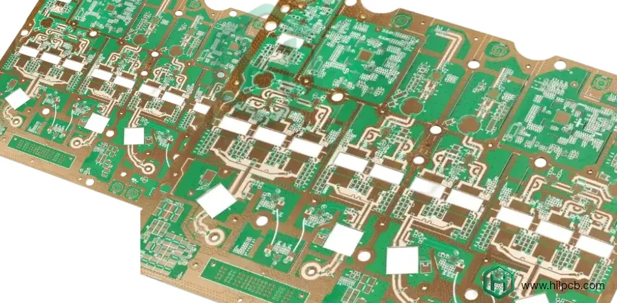
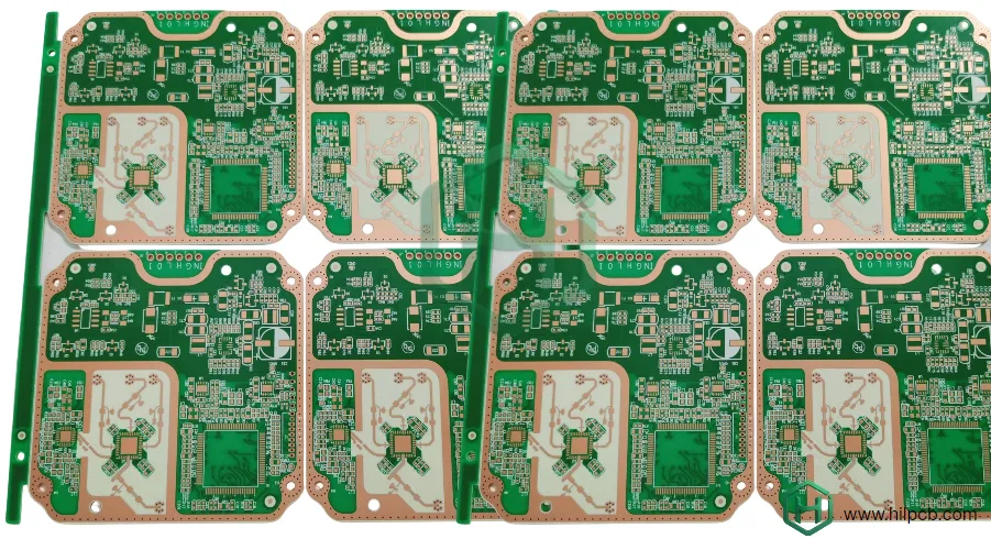
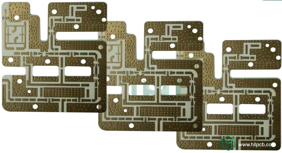
The Rogers RO4000 series is the industry-standard for high-frequency PCBs, offering excellent electrical performance with compatibility to standard manufacturing processes. Used in applications ranging from cellular base station power amplifiers to automotive radar, satellite communication, and aerospace avionics, RO4000 supports RF and microwave circuits from 500 MHz to 40 GHz.
What sets RO4000 apart from FR4 and PTFE materials is its low loss tangent, stable dielectric properties, and processing compatibility with conventional PCB equipment. This combination provides RF performance similar to PTFE laminates while allowing cost-effective production. Our comprehensive RO4000 manufacturing capabilities, including RO4003C, RO4350B, RO4360G2, and RO4835, ensure that engineers can select the right materials for their specific frequency and power requirements across various industries.
Why is Rogers RO4000 Ideal for High-Frequency Applications?
The Rogers RO4000 series is ideal for high-frequency designs due to its superior material properties and manufacturing compatibility, making it the material of choice for RF and microwave circuits.
Material Composition and Architecture:
RO4000’s hydrocarbon ceramic-filled composite combines ceramic microspheres with a hydrocarbon resin matrix, offering consistent electrical performance and low anisotropy across all axes. This structure eliminates the typical variation seen in FR4 boards and improves impedance tolerance, making it a reliable choice for high-frequency applications. Its uniform filler distribution further enhances predictable RF performance, offering engineers a material that excels in both stability and manufacturability.
Dielectric Constant and Low Loss Tangent:
RO4000 materials, such as RO4350B and RO4003C, maintain a stable dielectric constant and low loss tangent, ensuring minimal signal loss even at high frequencies. For example, RO4350B has a dielectric constant of 3.48 and a loss tangent of 0.0037, which translates to only 0.3 dB of insertion loss at 10 GHz. RO4003C offers an even lower loss tangent of 0.0027, improving system efficiency and extending range, while minimizing thermal management requirements. These properties make RO4000 ideal for power amplifiers, antenna systems, and test equipment where low loss and precision are critical.
Manufacturing Compatibility:
RO4000’s compatibility with standard PCB manufacturing processes like drilling, plating, etching, and imaging makes it more cost-effective than PTFE-based materials. Unlike PTFE, which requires special handling, RO4000 processes using conventional tools and equipment, reducing overall production costs. Its compatibility with standard FR4 PCB processing also means that manufacturers can use the same equipment for both materials, offering a cost-effective solution for high-frequency designs that require both precision and scalability.
In summary, RO4000’s low loss, stable dielectric properties, and ease of manufacturing make it the material of choice for a wide range of RF and microwave applications, ensuring high performance and reliability in demanding environments.

Low Loss and High Performance: Advantages of RO4000 PCBs
The low-loss characteristics of RO4000 materials translate into tangible system-level benefits across diverse high-frequency applications.
Extended Range in Wireless Systems:
Every decibel of RF path loss directly reduces system range or requires increased transmit power:
Link Budget Analysis:
For a typical wireless system:
- Transmit power: 1W (+30 dBm)
- PCB trace loss (2" on RO4350B vs. FR4 at 2.4 GHz): 0.2 dB vs. 0.7 dB
- 0.5 dB savings in trace loss = 12% range increase (free-space propagation)
Practical Applications:
- Cellular Base Stations: Longer coverage radius reducing infrastructure cost
- WiFi Access Points: Improved coverage in enterprise deployments
- LoRa IoT Networks: Extended sensor reach enabling sparser gateway deployment
- Satellite Terminals: Improved link margin enabling smaller antennas
This performance advantage justifies RO4000's material premium in applications where range, coverage, or link reliability are critical.
Reduced Power Consumption:
Lower loss enables system designers to reduce transmit power while maintaining link reliability:
Power Savings:
Using the same 0.5 dB loss reduction example:
- Can reduce PA output from 1W to 0.85W for same radiated power
- 15% power reduction in PA stage
- Cascading savings in DC-DC converters, thermal management, battery capacity
Battery-Powered Applications:
For IoT devices, wearables, and portable equipment:
- Longer battery runtime extending replacement intervals
- Smaller batteries reducing device size and weight
- Reduced thermal generation improving user comfort (wearables)
Our flex PCB and rigid-flex PCB designs combining RO4000 RF sections with flexible interconnects enable innovative wearable and portable product forms.
Improved Signal Integrity:
Beyond insertion loss, RO4000's low loss tangent reduces signal distortion:
Phase Linearity:
Frequency-dependent loss creates group delay variation—distorting wideband signals:
- RO4000's flat loss versus frequency maintains phase linearity
- Critical for wideband communication systems (5G, radar, test equipment)
- Enables higher-order modulation schemes (256-QAM, 1024-QAM) with lower error rates
Noise Figure Preservation:
In receiver RF front-ends, passive loss ahead of the LNA directly degrades system noise figure:
- Every 0.1 dB loss reduction improves sensitivity proportionally
- RO4000 enables more sensitive receivers without expensive low-noise amplifiers
- Critical for radar, SATCOM, and radio astronomy applications
Passive Component Performance:
Filters, couplers, and power dividers benefit from RO4000's loss characteristics:
Filter Insertion Loss:
Microstrip or stripline filters inherently lossy—dielectric and conductor loss accumulate:
- 5-section bandpass filter on FR4 at 10 GHz: ~3-4 dB insertion loss
- Same filter on RO4350B: ~1.5-2.0 dB insertion loss
- 2 dB improvement = 60% more signal power transmitted
Coupler Directivity:
Directional couplers used for power monitoring or combining require high isolation:
- Loss in coupling section degrades directivity
- RO4000's low loss enables better isolation and coupling flatness
- Critical for phased array beam steering and power combining
Our high-speed PCB designs incorporate these passive components with performance optimization leveraging RO4000 properties.
Temperature Stability:
Consistent performance across temperature extremes enables deployment in challenging environments:
Automotive Radar:
77-81 GHz automotive radar operates in engine compartments:
- Temperature range: -40°C to +125°C
- RO4000's stable εr maintains radar calibration across temperature
- Consistent target detection without temperature compensation algorithms
Outdoor Telecommunications:
Base station equipment faces daily temperature cycles:
- Morning low: -20°C to evening high: +60°C (solar heating)
- RO4000 maintains phase relationships in phased arrays
- Frequency stability in oscillators and filters
Aerospace Applications:
Aircraft avionics experience extreme temperature gradients:
- High-altitude cruise: -55°C ambient
- Ground operations: +75°C tarmac temperature
- RO4000 enables reliable operation without thermal recalibration
High-Power Handling:
RO4000's thermal properties support high-power RF applications:
Thermal Conductivity:
RO4350B: 0.62 W/m·K (vs. 0.3 W/m·K for standard FR4)
- Improved heat dissipation from power amplifiers
- Enables higher power density in compact layouts
- Reduces hot-spot temperatures improving reliability
Power Amplifier Modules:
Combining RO4000 RF substrate with metal core PCB heat spreaders:
- RO4000 provides RF performance for matching networks and output filters
- Metal core conducts heat away from PA die and bias circuits
- Hybrid construction optimizes both electrical and thermal performance

Applications of RO4000 PCBs in RF and Microwave Circuits
- Cellular Base Station Power Amplifiers (PAs)
- Power Amplifier Matching Networks
- Bias Distribution Networks for high-current DC bias
- Harmonic Filtering in RF power amplifiers
- Phased Array Antennas for radar and communication systems
- Patch Antenna Arrays for GPS, SATCOM, WiFi, and 5G
- Antenna Couplers and Duplexers for signal splitting and isolation
- Vector Network Analyzers (VNAs) for RF signal testing
- Signal Generators for RF signal calibration and testing
- Spectrum Analyzers for RF signal measurements
- Automotive Radar for ADAS (Advanced Driver Assistance Systems)
- Frequency Generation for mmWave Radar in automotive and communications
- RF Front-End Circuits in automotive radar
- Test Equipment for RF performance validation (e.g., oscillators, mixers, filters)
Why Choose Rogers RO4000 for Your Design?
Material selection involves trade-offs between performance, cost, and manufacturing compatibility. RO4000 offers compelling advantages:
Performance vs. Cost Sweet Spot:
Compared to alternatives:
- vs. Standard FR4: 3-5× better loss tangent at 10 GHz, justifying 2-3× material cost for RF-critical applications
- vs. PTFE Laminates: 90% of RF performance at 60% of material cost, with significantly lower manufacturing cost
- vs. Ceramic Substrates: Lower cost, easier processing, better suited for large-area boards
Manufacturing Ecosystem:
Broad industry adoption means:
- Most PCB manufacturers have RO4000 experience and established processes
- Material availability from distributors reducing lead time
- Component vendors provide reference designs and application notes
- Extensive literature and design tools available
Proven Reliability:
Decades of field history demonstrate:
- Passing automotive qualification (AEC-Q200, -40°C to +150°C)
- Military and aerospace approvals (MIL-PRF-55110, IPC-6012 Class 3)
- Telecom NEBS compliance for 20+ year service life
- Our turnkey assembly experience confirms consistent manufacturing reliability
Design Flexibility:
RO4000 series offers options for different applications:
- RO4003C: Lowest loss (Df 0.0027) for demanding applications
- RO4350B: Industry standard balance of performance and cost
- RO4360G2: Higher εr (6.15) enabling more compact designs
- RO4835: Highest frequency capability (100+ GHz) for mmWave
This flexibility enables designers to optimize material selection for specific requirements rather than accepting one-size-fits-all compromises.
How to Get Fast Quotes and Delivery for Rogers RO4000 PCBs
RO4000 material availability and established manufacturing processes enable competitive lead times:
Quotation Process:
Information Required:
- Gerber files, drill files, and fabrication drawings
- RO4000 grade specification (RO4003C, RO4350B, etc.)
- Copper weight requirements
- Surface finish selection
- Impedance control requirements and tolerances
- Quantity (prototype, pilot, production)
Turnaround:
- Standard quotes: 24-48 hours with DFM analysis
- Complex designs: 2-3 days including impedance modeling
- Volume pricing: 3-5 days including material cost optimization
Manufacturing Lead Times:
Prototype Quantities (5-25 boards):
- Material procurement: 5-7 days (RO4350B and RO4003C typically stocked)
- Fabrication: 10-15 days
- Total: 15-20 working days
Production Quantities (100+ boards):
- Material procurement: 7-10 days (with forecasting)
- Fabrication: 15-20 days
- Total: 20-28 working days
Expedited Services:
- Quick-turn prototypes: 7-10 days (premium pricing)
- Material expediting: Coordinating with Rogers for faster delivery
- Weekend processing: Available for critical deadlines
Our small batch assembly supports RO4000 prototype builds while large volume assembly provides optimized production pricing.
Cost Optimization Strategies:
Material Utilization:
- Standard sheet sizes (12"×18", 18"×24")
- Efficient panelization maximizing boards per sheet
- Sharing tooling across similar designs
- Volume commitments enabling material purchasing optimization
Hybrid Stack-Ups:
- Using RO4000 only on RF-critical layers
- FR4 for power distribution and digital signals
- Reducing total material cost 30-50%
Design Considerations:
- Standard thickness cores (5, 10, 20 mil) avoiding special procurement
- Copper weights matching sheet availability (1 oz, 2 oz standard)
- Layer counts optimized for routing density vs. cost trade-off
Ready to Start Your Rogers RO4000 PCB Project?
Our engineering team brings extensive experience with Rogers RO4000 materials across telecommunications, automotive radar, aerospace, and RF test equipment applications. We understand the design trade-offs, manufacturing nuances, and performance optimization strategies that ensure your high-frequency circuits achieve target specifications. Contact us today to discuss your RO4000 project requirements and receive a detailed quotation within 24 hours.

