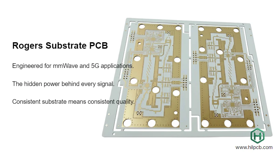
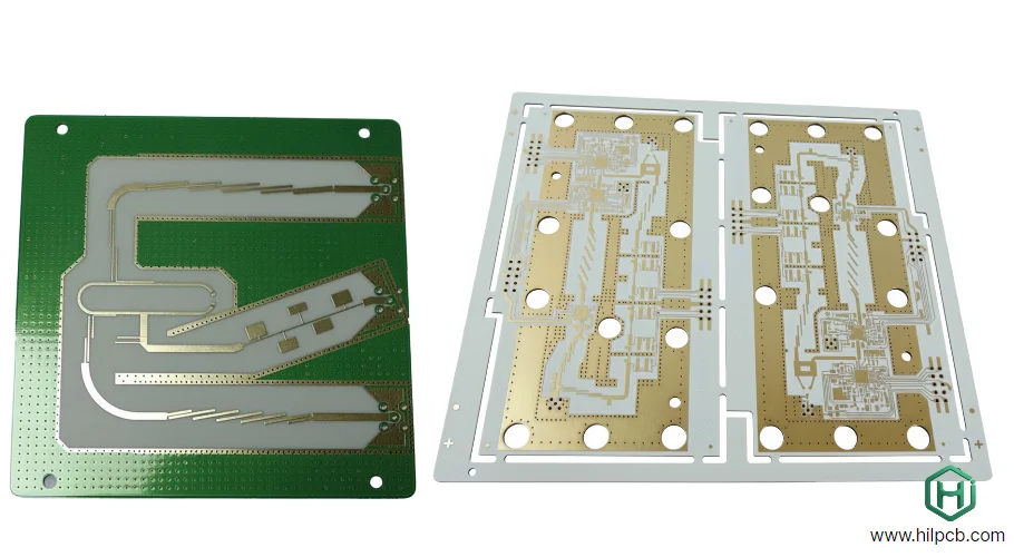
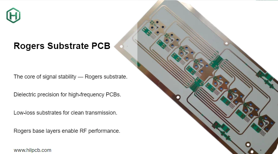
Selecting the right Rogers substrate material can make or break your RF and microwave project. At HILPCB, we manufacture Rogers substrate PCBs for applications from 5G base stations to automotive radar systems. Our engineering team has fabricated thousands of Rogers boards and learned which materials perform best for different frequency ranges and cost requirements.
This guide provides practical comparison data to help you choose between RO4003C, RO4350B, RO5880, and other Rogers materials based on actual manufacturing experience and measured performance.
Rogers Material Families: Performance and Cost Comparison
Rogers Corporation offers several substrate families optimized for different frequency ranges and applications. Understanding the differences is essential for cost-effective design.
RO4000 Series (Hydrocarbon Ceramic)
The RO4000 series provides the best balance of RF performance and manufacturability:
- RO4003C: Dk=3.38, tan δ=0.0027 @ 10GHz, most cost-effective option
- RO4350B: Dk=3.48, tan δ=0.0037 @ 10GHz, lead-free compatible
- Processing compatible with standard FR4 PCB equipment
- Suitable for frequencies up to 40GHz
- Cost: 3-4x standard FR4 material
RO3000 Series (Ceramic-Filled PTFE)
Advanced ceramics-filled PTFE for demanding applications:
- RO3003: Dk=3.00, tan δ=0.0013 @ 10GHz
- RO3006: Dk=6.15, tan δ=0.0020 @ 10GHz
- Better dimensional stability than pure PTFE
- Frequency range: DC to 77GHz
- Cost: 6-7x standard FR4 material
RO5000 Series (Pure PTFE)
Lowest loss materials for extreme performance:
- RO5880: Dk=2.20, tan δ=0.0009 @ 10GHz
- RO5870: Dk=2.33, tan δ=0.0012 @ 10GHz
- Minimum insertion loss for critical paths
- Frequency range: DC to 100GHz+
- Cost: 8-10x standard FR4 material
Our high-frequency PCB manufacturing capabilities support all Rogers material families with specialized processes for PTFE-based substrates.

RO4003C vs RO4350B: Which Hydrocarbon Ceramic to Choose
Both RO4003C and RO4350B are workhorse materials for most RF applications, but they have important differences.
Key Specifications Comparison
| Property | RO4003C | RO4350B |
|---|---|---|
| Dielectric Constant @ 10GHz | 3.38 ±0.05 | 3.48 ±0.05 |
| Dissipation Factor @ 10GHz | 0.0027 | 0.0037 |
| Thermal Coefficient (ppm/°C) | 40 | 32 |
| Maximum Frequency | 40GHz | 35GHz |
| Lead-Free Compatible | No | Yes |
| UL 94 Rating | V-0 | V-0 |
| Relative Cost | 1.0x | 1.2x |
When to Use RO4003C:
- Frequency range below 40GHz
- Cost-sensitive designs
- Standard lead-tin soldering acceptable
- Best insertion loss performance needed
- Applications: 5G sub-6GHz, WiFi 6E, GNSS receivers
When to Use RO4350B:
- Lead-free assembly required (RoHS compliance)
- Automotive applications (IATF 16949)
- Medical devices (regulatory requirements)
- Better thermal stability needed (-40°C to +125°C)
- Applications: Automotive radar, medical imaging, industrial controls
Our multilayer PCB capabilities allow hybrid stackups combining RO4003C or RO4350B with FR4 layers for cost optimization—typically 30-40% material cost savings versus all-Rogers construction.
RO5880 for Ultra-Low Loss mmWave Applications
When your application demands absolute minimum insertion loss, RO5880 is the standard choice for frequencies above 40GHz.
Performance Advantages:
- Lowest loss tangent: 0.0009 @ 10GHz (3x better than RO4003C)
- Low dielectric constant: 2.20 (wider traces = easier fabrication)
- Excellent phase stability over temperature
- Frequency capability: DC to 110GHz
- Ideal for: 77GHz automotive radar, E-band backhaul, satellite terminals
Manufacturing Considerations:
RO5880 is PTFE-based and requires specialized processing:
- Plasma treatment before plating (adhesion critical)
- Longer lamination cycles (90-120 minutes vs 60 minutes)
- Specialized drilling parameters (softer material)
- Cannot use standard HDI PCB laser drilling
- Requires careful handling (material deforms easily)
Measured Insertion Loss Data (50Ω microstrip, 5cm length @ 77GHz):
- RO4003C: -1.2 dB
- RO3003: -0.7 dB
- RO5880: -0.5 dB
For applications where every 0.1dB matters—such as phased array radar or satellite ground terminals—RO5880's performance advantage justifies the premium cost.
We manufacture RO5880 boards with high thermal PCB backing layers to manage heat in power amplifier sections while maintaining RF performance.

Hybrid Stackup Strategies for Cost Optimization
Using Rogers material for the entire board is often unnecessary and expensive. Hybrid stackups combine Rogers layers where needed with standard materials elsewhere.
Typical 6-Layer Hybrid Example:
- Layer 1: RO4003C (RF circuits, antenna feeds)
- Layer 2: Prepreg + FR4 core (ground plane)
- Layer 3-4: High-Tg PCB material (digital circuits, power distribution)
- Layer 5: Prepreg + FR4 core (ground plane)
- Layer 6: RO4003C (RF circuits, antenna feeds)
Cost Savings Analysis (100x100mm board, qty 100):
- All-RO4003C: $285 material cost per board
- Hybrid (RO4003C + FR4): $165 material cost per board
- Savings: 42% with minimal RF performance impact (<0.2dB)
Design Considerations for Hybrids:
- CTE mismatch between Rogers and FR4 (use balanced stackup)
- Via transitions between material types (add extra ground vias)
- Prepreg selection critical (Rogers recommends specific types)
- Thermal expansion differences (consider operating temperature range)
Our engineering team provides free stackup optimization for hybrid designs using Rogers + FR4, Rogers + ceramic PCB, or Rogers + metal core PCB combinations.
Rogers Substrate Material Availability and Lead Times
In-Stock Materials at HILPCB:
- RO4003C: 0.203mm, 0.305mm, 0.508mm, 0.813mm
- RO4350B: 0.254mm, 0.508mm, 0.762mm
- Lead time: 2-3 days to start fabrication
Special Order Materials:
- RO5880: All thicknesses, 7-10 days procurement
- RO3003/RO3006: 10-14 days procurement
- Custom thickness combinations: 14-21 days
For prototype and small batch assembly projects, we maintain RO4000 series inventory to enable fast turnaround. Production volumes benefit from our large volume assembly pricing and material procurement advantages.
Quality Control for Rogers Substrate PCBs
Every Rogers substrate board we manufacture undergoes rigorous testing:
Material Verification:
- Certificate of conformance from Rogers Corporation
- Lot number traceability for aerospace/automotive
- Dielectric constant measurement (split-post resonator)
- Thickness measurement (±0.025mm tolerance)
Fabrication Quality:
- Impedance testing: TDR measurement on test coupons
- Microsection analysis: copper thickness, via quality
- Single and double layer PCB dimensional accuracy
- Surface finish verification: ENIG thickness, gold purity
Assembly Quality:
- X-ray inspection: BGA void analysis, via fill quality
- AOI: Component placement, solder joint quality
- Functional testing: RF performance validation
- Through-hole assembly pull test: mechanical strength
We are ISO 9001:2015 and IATF 16949 certified with full material traceability for automotive and aerospace applications requiring Rogers substrates.
Frequently Asked Questions – Rogers Substrate Selection
Q1: Can I use Rogers material with standard FR4 in the same stackup?
A: Yes, hybrid stackups are common and cost-effective. Use Rogers for RF layers and FR4 for digital/power layers. Critical points: CTE matching, proper prepreg selection, and balanced construction to prevent warpage. We provide free stackup design consultation.
Q2: What's the minimum order quantity for Rogers substrate PCBs?
A: No MOQ restrictions. We manufacture prototypes (1-5 pieces) to production volumes (10,000+ units). Pricing scales with volume, but even small quantities are economical due to our in-stock material inventory.
Q3: How do I calculate impedance for Rogers materials?
A: We provide free impedance calculation service using Rogers substrate data. Submit your stackup requirements and target impedance—our engineering team calculates trace widths and provides detailed reports within 24 hours.
Q4: Can Rogers substrate boards be assembled with standard SMT processes?
A: RO4000 series: Yes, standard processes work with modified reflow profiles. RO5000/PTFE series: Requires lower peak temperature (240°C vs 250°C) and extended soak time. Our assembly team has Rogers-specific profiles optimized for reliability.
Q5: What surface finish works best with Rogers substrates?
A: ENIG (Electroless Nickel Immersion Gold) is preferred for RF applications—provides excellent solderability, wire bonding capability, and low contact resistance. Immersion silver acceptable for cost-sensitive designs. HASL not recommended due to high temperature stress.

