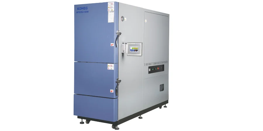
At Highleap PCB Factory (HILPCB), we integrate thermal shock testing as a key step in our PCB manufacturing and assembly process. Our capabilities include air-to-air and liquid-to-liquid testing, temperature cycling, and material behavior analysis. This approach ensures solder joint integrity, via reliability, and material stability under extreme thermal conditions common in aerospace, automotive, and industrial applications.
Core Thermal Shock Testing Principles and Methodology Selection
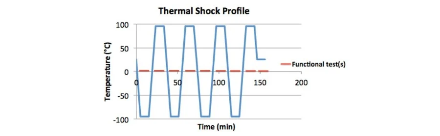
Thermal shock testing replicates sudden temperature shifts to identify mechanical stress failures caused by mismatched coefficients of thermal expansion (CTEs) among different materials. At HILPCB, we select from multiple test technologies based on board type, thermal profile, and end-use reliability targets.
Key Technologies:
- Air-to-Air Chambers: Controlled thermal exposure with transition rates exceeding 30°C/min for real-world simulation
- Liquid-to-Liquid Systems: Extreme shock through immersion, delivering >100°C/min transitions
- Two-Zone Automation: Separate hot and cold chambers with robotic transfer systems
- Programmable Profiles: Customizable cycles from -80°C to +225°C, with soak times for full heat transfer
- Real-Time Monitoring: Continuous tracking of electrical continuity and temperature gradients
- Failure Detection Systems: Inline alerts for microfractures and delamination
- Statistical Reliability Tools: Data collection for Weibull modeling and field failure prediction
Our implementation strategy emphasizes selecting optimal methods tailored to board technologies like high-thermal PCBs or ceramic PCBs, balancing test rigor with production efficiency.
Temperature Cycling Protocols and Environmental Stress Simulation
Thermal shock testing simulates operational extremes across short timeframes to accelerate aging effects. Selection of testing protocols depends on product application, required life cycle data, and environmental exposure.
Air-to-Air Simulation: Used for products subject to ambient swings (e.g., automotive or outdoor electronics). Transition speeds up to 50°C/min support realistic fatigue stress. Chambers maintain ±2°C accuracy to ensure repeatable results.
Liquid-to-Liquid Transition: Suitable for high-stress validation such as power electronics and mission-critical designs. Transition rates exceed 100°C/min, rapidly inducing thermal stress throughout PCBs with minimal thermal lag. Essential for validating high-density interconnect (HDI) and metal-core boards.
Thermal Profile Optimization: We tailor sequences from -55°C to +125°C for commercial PCBs, and up to -65°C to +200°C for aerospace standards. Soak times, ramp rates, and number of cycles are adjusted according to board mass and configuration.
Failure Mechanisms and Material Behavior Analysis
Thermal shock can trigger several distinct failure modes. Understanding these is critical to both design robustness and predictive reliability.
Common Failures:
- Plated Through-Hole Cracking: Barrel-wall fractures from CTE mismatch
- Solder Joint Fatigue: Joint cracking due to cyclic thermal expansion
- Delamination: Layer separation at resin-prepreg or copper interfaces
- Via Fracture: Cracking at annular rings or pad transitions
- Lead Cracking: Mechanical breakage in package leads during rapid cooling
- Pad Lift-off: Trace delamination or SMT pad failure from surface strain
- Wire Bond Damage: Separation in microelectronics due to mismatched CTE
Material CTEs define stress severity. For example, standard FR4 may expand 50–70 ppm/°C through thickness, while Rogers PCBs offer improved thermal compatibility, reducing stress concentrations.
Implementation of Thermal Shock Testing in Production Environments
Integrated QA and Monitoring
Thermal shock testing is embedded in our quality workflow. Incoming component validation, process-specific testing, and final inspection ensure conformance. In-process testing helps isolate issues in multilayer and flex PCB assemblies before volume production.
Chamber Technology and Throughput Optimization
Chambers are selected based on PCB size, thermal mass, and throughput. For large volume assembly, automated loading systems and programmable logic reduce manual handling, enhancing accuracy and efficiency.
Data Logging and Traceability
All test results are digitally logged and linked to manufacturing lots. This ensures compliance with traceability standards in industries such as aerospace and medical electronics, supporting field failure analysis and warranty coverage.
Advanced Failure Analysis and Reliability Modeling
We deploy multiple analysis techniques post-test to understand failure origins:
- Cross-section Analysis: Reveals internal fractures or material voids
- X-ray Imaging: Detects hidden cracks and delamination
- Fractography: Identifies crack initiation and propagation paths
- Thermal Modeling: Correlates physical test data with design parameters
Reliability predictions are generated using statistical models:
- Weibull Distribution: Defines cycle-to-failure probability
- Arrhenius Models: Estimate failure rates under accelerated stress
- Environmental Conditioning: Combines vibration, humidity, and pre-aging for field correlation
Boards like flex PCBs benefit from such combined tests to simulate deployment in rugged environments.
HILPCB’s Thermal Reliability Strategy
At HILPCB, we integrate thermal reliability from the design phase through final assembly.
- Design Stage Support: CTE mapping, stress simulation, and material selection
- Process Alignment: Controlled reflow profiles, optimized via designs, and robust soldering for SMT assemblies
- Testing Infrastructure: Multiple thermal chambers, inline data capture, and failure diagnostics available for both prototypes and full-scale production
Thermal Shock Testing – FAQ
What temperature range is used in thermal shock testing?
Typical ranges include -55°C to +125°C for commercial and up to -65°C to +200°C for aerospace/military.
How is thermal shock different from thermal cycling?
Thermal shock has rapid temperature changes (>30°C/min), while thermal cycling uses slower transitions (<5°C/min).
How many cycles are standard?
Depends on reliability standards—10–100 for consumer, 500–1000+ for industrial/military.
Can thermal shock data predict field reliability?
Yes, when linked with field data and statistical models like Arrhenius or Weibull.
What materials offer best thermal shock resistance?
High-Tg laminates, ceramic substrates, and CTE-matched composites perform best.
How are test failures detected?
Via electrical monitoring, cross-sectioning, and imaging (X-ray/SEM) to locate and classify failure sites.