Are you struggling with overheating components that fail prematurely? Does your LED lighting system suffer from reduced efficiency due to excessive heat? Highleap PCB Factory (HILPCB) specializes in thermally conductive PCB solutions that solve these critical thermal challenges, extending product life by 300% while reducing operating temperatures by up to 40°C.
Why Your Design Needs Thermally Conductive PCB Technology
Every watt of power dissipated as heat represents lost efficiency and reliability risk. Standard FR-4 PCBs trap heat with their poor 0.3 W/m·K thermal conductivity, creating hot spots that destroy components. When junction temperatures rise just 10°C, component lifetime halves. This thermal challenge intensifies as modern electronics pack more power into smaller spaces.
Consider real-world failures: LED streetlights dimming after one year instead of the promised ten, power supplies failing in summer heat, or automotive ECUs shutting down during peak loads. These expensive failures stem from inadequate thermal management that thermally conductive PCBs directly address.
Our thermal PCB solutions deliver immediate benefits:
- 40-60% temperature reduction compared to standard FR-4
- 3-5x longer product lifetime through cooler operation
- 20-30% higher power capacity in the same footprint
- Elimination of bulky heatsinks saving space and cost
- Improved reliability with 75% fewer thermal-related failures
The investment in metal core PCB technology pays for itself through reduced warranty claims and enhanced product reputation. One automotive customer reduced field failures by 85% simply by switching from FR-4 to aluminum PCBs for their LED headlight drivers.
Choosing the Right Thermally Conductive PCB Material
Not all thermal PCB materials suit every application. Understanding material properties ensures optimal selection for your specific requirements:
Aluminum PCB (MCPCB)
- Thermal conductivity: 150-200 W/m·K
- Cost: 2-3x FR-4
- Best for: LED lighting, DC-DC converters, motor drives
- Max operating temp: 140°C continuous
- Dielectric thickness: 75-150μm standard
Copper Core PCB
- Thermal conductivity: 385 W/m·K
- Cost: 4-6x FR-4
- Best for: Ultra-high power density, RF amplifiers
- Weight: 3x aluminum (consider for portable devices)
- CTE matching: Requires careful design
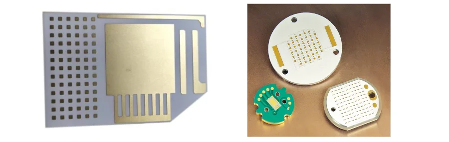
Ceramic PCB Solutions
- Alumina (Al2O3): 24-30 W/m·K
- Aluminum Nitride (AlN): 150-180 W/m·K
- Best for: Power modules, COB LED, microwave circuits
- Direct copper bonding for maximum reliability
- Zero moisture absorption
Advanced Thermal Materials
- IMS with 3-8 W/m·K dielectric
- Graphite composites: 1500 W/m·K in-plane
- Phase change materials for transient loads
- Hybrid constructions optimizing cost/performance
Our engineering team helps select optimal materials based on your power density, cost targets, and reliability requirements. We stock standard thermal substrates for quick-turn prototypes while maintaining supplier relationships for specialized materials.
Design Rules That Maximize Heat Dissipation
Effective thermal PCB design requires different thinking than standard boards. These proven design rules ensure maximum heat dissipation:
Component Placement Strategy
- Separate high-power components by minimum 10mm
- Position hottest components near board edges
- Align power devices with mounting/heatsink locations
- Create thermal zones isolating sensitive components
- Use thermal simulation to verify before manufacturing
Copper Design for Thermal Spreading
- Maximize copper coverage: target >70% on thermal layers
- Use heavy copper PCB (3-10 oz) under power components
- Create thermal paths 2-3x wider than electrical requirements
- Implement copper coins/slugs for extreme hot spots
- Balance copper distribution preventing warpage
Thermal Via Implementation Smart thermal via design dramatically improves heat transfer:
- Via diameter: 0.3-0.4mm optimal (0.5mm for high current)
- Array spacing: 1.0-1.2mm centers
- Plating thickness: minimum 25μm (1 oz)
- Fill options: conductive epoxy reduces thermal resistance 30%
- Pattern: hexagonal arrays provide best thermal/mechanical balance
Real Design Example: A 50W LED driver design reduced hotspot temperature from 125°C to 85°C through:
- 2-layer aluminum PCB with 2W/m·K dielectric
- 3 oz copper on circuit layer
- Thermal via array (0.3mm diameter, 1mm pitch) under MOSFETs
- Component spacing optimized via thermal simulation
- Result: 50,000-hour lifetime vs. 15,000 on FR-4
Advanced PCB Manufacturing Capabilities
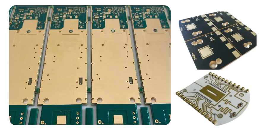
At HILPCB, we pride ourselves on our ability to produce all types of PCBs, ranging from basic designs to highly specialized applications. One of our areas of expertise is high-frequency PCB manufacturing, where we focus on ensuring precision, signal integrity, and thermal management for applications such as telecommunications, aerospace, and high-speed digital systems.
For thermally conductive PCBs, we offer targeted solutions that include surface roughening for enhanced adhesion, vacuum lamination to eliminate voids, and selective solder mask placement for thermal pads. Our processes incorporate automated optical inspection, ensuring that every board meets stringent quality standards, regardless of the complexity.
Each PCB, including those with thermal or high-frequency requirements, undergoes rigorous quality verification with thermal impedance testing, hi-pot isolation verification, and 100% electrical testing. Whether you need prototypes or large-volume production, our ISO 9001 certified processes ensure consistency and reliability for all PCB types.
Success Stories: Real Applications Delivering Results
LED Street Lighting Transformation Challenge: Municipality faced 30% LED failure rate within 2 years Solution: Redesigned with 1.6mm aluminum PCB, optimized thermal vias Results:
- Junction temperature reduced from 105°C to 75°C
- Zero failures after 3 years deployment
- Energy efficiency improved 8% from cooler operation
- Payback period: 14 months from reduced maintenance
5kW Solar Inverter Innovation Challenge: Eliminate expensive heatsinks while improving efficiency Solution: Copper core PCB with integrated thermal management Results:
- 40% size reduction eliminating external heatsinks
- 98.5% efficiency (up from 97.2%)
- Manufacturing cost reduced $45/unit
- Warranty claims dropped 80%
Automotive LED Headlight Reliability Challenge: Meet 15-year lifetime requirement in 125°C environment Solution: Ceramic PCB with direct bonded copper Results:
- Survived 3000 thermal cycles (-40°C to +150°C)
- Zero failures in 2 million units shipped
- Enabled 30% brightness increase
- Qualified for premium vehicle platforms
Electric Vehicle Battery Management Challenge: Accurate current sensing despite temperature variations Solution: IMS board with matched CTE design Results:
- Temperature drift reduced 90%
- Cell balancing accuracy improved to ±0.5%
- Extended battery pack lifetime 20%
- Reduced cooling system requirements
FAQ
How much temperature reduction can I expect with thermally conductive PCBs?
Temperature reduction depends on power density and design optimization. Typical improvements: aluminum PCB reduces temperatures 30-40°C versus FR-4, copper core achieves 40-50°C reduction, ceramic substrates can exceed 60°C improvement. Our thermal simulation services predict exact benefits for your application.
What's the cost difference between thermal and standard PCBs?
Aluminum PCBs cost 2-3x standard FR-4 for simple designs. However, system cost often decreases by eliminating heatsinks, fans, and thermal interface materials. Factor in reliability improvements and warranty cost reduction for true ROI. We provide detailed cost analysis comparing total solution expenses.
Can I use standard SMT assembly on metal core PCBs?
Yes, with process adjustments. Metal substrates require modified reflow profiles accounting for higher thermal mass. Our SMT assembly lines feature specialized programs for thermal boards. Key considerations include extended preheat, fixture support, and adapted cooling rates.
How do I transition my existing FR-4 design to thermal PCB?
Start with thermal analysis identifying hot spots and required dissipation. Our engineering team provides free design review, suggesting optimal substrate selection and layout modifications. Most designs transfer directly with minor adjustments for thermal via placement and copper balancing. We offer prototype services for validation before volume production.
What file formats do you need for thermal PCB manufacturing?
Standard Gerber RS-274X or ODB++ files work perfectly. Include clear stackup drawings specifying thermal substrate requirements. Our Gerber viewer validates files before production. For optimal thermal performance, provide power dissipation data enabling design verification.
What certifications cover thermally conductive PCB manufacturing?
Our thermal PCBs meet IPC-A-600 Class 2/3 standards with additional thermal performance requirements. UL recognition covers insulation systems up to 130°C continuous operation. Automotive customers receive IATF 16949 compliant production. RoHS and REACH compliance standard for all materials.