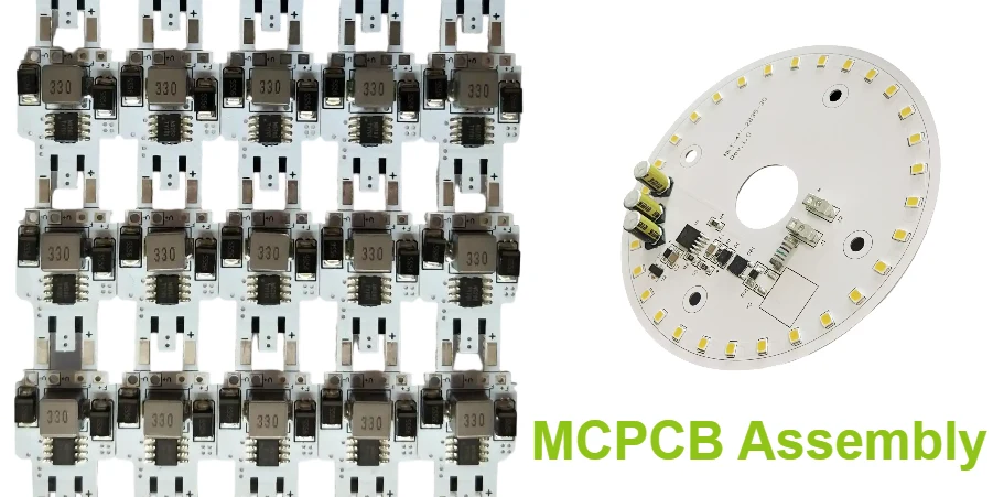
At Highleap PCB Factory, we provide end-to-end Metal Core PCB (MCPCB) assembly services designed for today's most demanding electronic applications. Our expertise goes far beyond LEDs and automotive boards – we support industrial power systems, renewable energy, telecom infrastructure, medical electronics, aerospace, and consumer devices. By combining specialized equipment, advanced thermal management processes, and decades of engineering experience, we deliver assemblies that meet strict performance and reliability requirements.
This complete guide explores MCPCB assembly techniques, process optimization strategies, quality control practices, and application-driven solutions, ensuring manufacturers can achieve consistent results across a wide range of high-power and thermally challenging designs.
Understanding MCPCB Assembly Challenges
Metal Core PCB assembly presents unique challenges compared to traditional FR-4 assembly, requiring specialized processes and equipment adaptations. The metal substrate's high thermal conductivity, which provides excellent heat dissipation during operation, creates assembly challenges requiring careful process control.
Thermal Mass Considerations: The aluminum or copper core PCB substrate acts as a massive heat sink during soldering, requiring modified reflow profiles and increased thermal energy. Standard reflow parameters fail to achieve proper solder joint formation due to rapid heat dissipation. Preheating becomes critical for temperature equalization across the board. Bottom-side heating compensates for substrate heat absorption. Extended soak zones ensure uniform temperature distribution before reflow.
Material Compatibility Issues: Metal substrates expand differently than components creating stress during thermal cycling. CTE mismatch between aluminum (23 ppm/°C) and ceramic components (6 ppm/°C) requires careful process design. Solder joint reliability depends on stress management through optimized pad design. Underfill or edge bonding provides mechanical reinforcement for critical components. Assembly sequence planning minimizes cumulative stress effects.
Surface Preparation Requirements: Aluminum substrates oxidize rapidly requiring special handling and preparation. Surface contamination significantly impacts solder joint reliability. Cleaning processes must remove oxidation without damaging the dielectric layer. Flux selection becomes critical for promoting proper wetting. Storage conditions and handling procedures prevent recontamination before assembly.
MCPCB vs FR-4 Assembly Comparison
| Parameter | Standard FR-4 | Aluminum MCPCB | Copper MCPCB |
|---|---|---|---|
| Preheat Temperature | 100-120°C | 120-150°C | 140-160°C |
| Soak Time | 60-90 seconds | 90-120 seconds | 120-150 seconds |
| Peak Temperature | 235-245°C | 245-255°C | 250-260°C |
| Time Above Liquidus | 45-60 seconds | 60-75 seconds | 65-80 seconds |
| Cooling Rate | 2-4°C/sec | 1-3°C/sec | 1-2°C/sec |
Solder Paste Printing Optimization
Precise solder paste application forms the foundation of reliable MCPCB assembly, requiring optimized stencil design and printing parameters accommodating substrate characteristics.
Stencil Design Considerations
Aperture Modifications: Increased paste volume compensates for substrate heat absorption during reflow. Typical aperture area ratio increases 10-20% compared to FR-4 designs. Home plate and D-shaped apertures improve paste release for fine-pitch components. Rounded corners prevent paste retention improving print consistency. Nano-coating reduces surface tension enhancing paste transfer efficiency.
Thickness Selection: Standard 0.12mm (5 mil) stencils suit most MCPCB applications. Stepped stencils accommodate mixed component technologies on single boards. 0.15mm (6 mil) thickness provides additional paste for high-thermal-mass components. Laser-cut apertures ensure smooth walls minimizing paste retention. Electroformed stencils offer superior accuracy for fine-pitch applications.
Printing Process Parameters
Machine Setup: Squeegee pressure adjustment compensates for substrate rigidity differences. Print speed reduction (20-40mm/s) improves paste transfer consistency. Separation speed optimization prevents paste stretching or tearing. Support fixtures prevent substrate flexing during printing. Automatic stencil cleaning maintains print quality over production runs.
Paste Selection: No-clean flux formulations prevent cleaning-related substrate damage. Type 4 or 5 powder improves fine-feature printing definition. Extended open time accommodates longer assembly processes. Halogen-free options meet environmental requirements. Thermal stability ensures consistent performance through extended profiles.
Component Placement Strategies
Accurate component placement on MCPCB substrates requires consideration of thermal expansion, placement force, and adhesive requirements unique to metal core boards.
Pick and Place Optimization
Machine Configuration: Vision system calibration accounts for substrate reflectivity variations. Placement force adjustment prevents component or substrate damage. Nozzle selection accommodates component variety while minimizing changeover. Fiducial recognition optimization handles different substrate colors. Component height sensing ensures accurate Z-axis positioning.
Placement Accuracy: Global fiducials on substrate corners maximize correction accuracy. Local fiducials near critical components improve fine-pitch placement. Panel warpage compensation maintains accuracy across large substrates. Temperature-controlled placement heads prevent thermal drift. Statistical process control monitors and maintains placement accuracy.
Adhesive Dispensing
Thermal Management: Thermally conductive adhesives enhance heat transfer for critical components. Dispensing patterns optimize coverage while minimizing material usage. Cure profiles balance adhesion strength with production throughput. UV-cure options enable selective bonding without thermal stress. Rework compatibility ensures serviceability when required.
Application Methods: Jet dispensing provides precise, non-contact adhesive application. Pin transfer ensures consistent dot size for chip components. Screen printing enables large-area underfill application. Needle dispensing accommodates irregular component geometries. Automated inspection verifies adhesive placement before component mounting.
Reflow Soldering Profile Optimization
Preheat Zone
- Ramp rate: 1.5-2°C/sec maximum
- Target: 150°C for aluminum substrates
- Duration: 90-120 seconds typical
- Bottom heating: 60-70% of top zones
Soak Zone
- Temperature: 150-180°C range
- Duration: 60-90 seconds minimum
- Flux activation optimization
- Temperature equalization critical
Reflow Zone
- Peak: 245-255°C for SAC305
- Time above liquidus: 60-75 seconds
- Peak dwell: 10-20 seconds
- Nitrogen atmosphere recommended
Cooling Zone
- Rate: 2-3°C/sec maximum
- Gradual cooling prevents stress
- Exit temperature: <40°C
- Forced cooling carefully controlled
Profile verification using thermal profiling systems essential for process validation
Selective Soldering for MCPCB
Selective soldering provides precise through-hole component assembly on MCPCB substrates, addressing challenges of traditional wave soldering with metal core boards.
Process Advantages
Thermal Control: Localized heating minimizes substrate thermal stress. Programmable preheat prevents thermal shock. Precise dwell time control ensures complete hole filling. Multi-point temperature monitoring maintains process control. Nitrogen atmosphere improves wetting and reduces oxidation.
Flexibility Benefits: Individual joint programming accommodates varying thermal masses. Multiple flux and solder types possible on single board. Component-specific parameters optimize each connection. No masking required reducing preparation time. Minimal thermal impact on adjacent SMT components.
Implementation Guidelines
Flux Application: Spray fluxing provides uniform coverage with minimal volume. Drop-jet fluxing enables precise application control. Flux activation time and temperature optimize wetting. No-clean formulations eliminate post-solder cleaning. Compatibility verification prevents substrate degradation.
Solder Parameters: Solder temperature 260-280°C for lead-free applications. Contact time 2-4 seconds per joint typically. Nitrogen flow rate 15-20 L/min for oxidation prevention. Wave height adjustment ensures complete barrel fill. Anti-bridging features prevent solder shorts.
Quality Control and Inspection
Comprehensive quality control throughout MCPCB assembly ensures reliability and performance meeting customer requirements. Our MCPCB reliability testing protocols validate long-term performance.
In-Process Monitoring
Solder Paste Inspection (SPI): 3D measurement validates paste volume and distribution. Height, area, and volume measurements ensure consistency. Real-time feedback enables immediate corrective action. Statistical trending identifies process drift before defects occur. Closed-loop communication with printer optimizes parameters.
Automated Optical Inspection (AOI): Post-placement inspection verifies component position and orientation. Post-reflow inspection identifies solder defects and component issues. 3D AOI provides enhanced defect detection capability. False call reduction through optimized programming and lighting. Statistical data collection enables continuous improvement.
Functional Testing
In-Circuit Testing (ICT): Electrical verification confirms circuit functionality. Component value measurement validates assembly accuracy. Boundary scan testing for complex digital circuits. Flying probe testing for prototype and low-volume production. Thermal testing validates heat dissipation performance.
Burn-In and Reliability: Temperature cycling confirms solder joint reliability. Power cycling validates thermal management effectiveness. Vibration testing ensures mechanical integrity. Environmental stress screening identifies infant mortality. Accelerated life testing predicts long-term reliability.
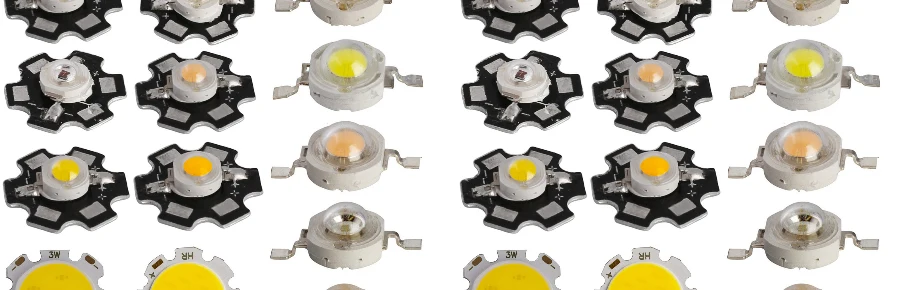
LED MCPCB Assembly Specifications
LED Types Supported
SMD LEDs: 3528, 5050, 5730, 2835
High Power: 1W, 3W, 5W, 10W
COB: 10W-300W arrays
UV/IR: Special handling available
Thermal Interface
TIM Types: Paste, pad, adhesive
Conductivity: 1-8 W/m·K options
Thickness: 50-200μm controlled
Coverage: >95% contact area
Quality Standards
IPC-A-610: Class 2/3 assembly
J-STD-001: Solder requirements
Inspection: 100% AOI + functional
Traceability: Full lot tracking
Production Capacity
SMT Lines: 8 high-speed lines
Capacity: 50M components/month
Minimum: 1 piece prototype
Maximum: 100K+ production
Advanced Assembly Technologies
Emerging technologies and advanced processes enhance MCPCB assembly capabilities addressing increasingly complex requirements.
Vapor Phase Soldering
Process Benefits: Uniform heating regardless of component mass or color. Maximum temperature limited by fluid boiling point. Void-free solder joints through controlled atmosphere. Reduced oxidation in inert vapor environment. Lower peak temperatures possible compared to convection.
MCPCB Applications: Large aluminum substrates with significant thermal mass. High-layer-count assemblies with varying copper densities. Mixed technology boards with diverse component types. Void-sensitive applications requiring superior joint quality. Temperature-sensitive components requiring minimal thermal stress.
Laser Soldering
Selective Processing: Non-contact localized heating preserves substrate integrity. Programmable energy delivery optimizes each joint. Real-time temperature monitoring ensures process control. Minimal thermal impact on adjacent components. Automated inspection validates joint quality.
Precision Applications: Fine-pitch components requiring accurate energy control. Thermally sensitive assemblies needing minimal heat exposure. Rework and modification without affecting entire assembly. Prototype development with frequent design changes. High-reliability applications demanding consistent joint quality.
Design for Assembly Guidelines
Optimizing MCPCB designs for assembly improves yields, reduces costs, and ensures reliable production. Following proper MCPCB design rules ensures manufacturability.
Pad Design Optimization
Thermal Considerations: Increased pad sizes accommodate thermal expansion mismatch. Thermal relief patterns balance soldering with heat dissipation. Via-in-pad designs require filling to prevent solder wicking. Copper balancing minimizes warpage during assembly. Solder mask defined pads improve registration accuracy.
Component Selection: Choose packages with compatible CTE characteristics. Consider component standoff height for cleaning and inspection. Evaluate temperature ratings for reflow profile compatibility. Select moisture sensitivity levels appropriate for process. Verify availability and lifecycle for production planning.
Panel Design
Manufacturing Efficiency: Optimize panel size for equipment capabilities. Include tooling holes for accurate registration. Add fiducials for vision system alignment. Implement bad board marking for in-process tracking. Design break-away tabs for easy depanelization.
Testing Access: Provide test points for in-circuit testing. Ensure probe access for flying probe testing. Include boundary scan chains for digital testing. Add thermal test points for performance validation. Design for automated handling and testing fixtures.
Cost Optimization Strategies
Balancing assembly quality with cost efficiency ensures competitive MCPCB solutions meeting market requirements. Our MCPCB cost analysis helps optimize your budget.
Process Selection
Volume Considerations: Manual assembly for prototypes and ultra-low volume. Semi-automated processes for small to medium batches. Fully automated lines for high-volume production. Flexible manufacturing cells for high-mix requirements. Dedicated lines for stable high-volume products.
Technology Trade-offs: Evaluate stencil versus dispensing for paste application. Compare selective versus wave soldering for through-hole. Assess vapor phase versus convection reflow benefits. Consider laser versus traditional selective soldering. Balance automation level with product complexity and volume.
Supply Chain Management
Component Procurement: Consolidate suppliers reducing management overhead. Implement vendor-managed inventory for stable products. Utilize consignment programs for high-value components. Establish alternates for critical components. Monitor lifecycle status preventing obsolescence issues.
Production Planning: Batch similar technologies maximizing efficiency. Schedule preventive maintenance minimizing downtime. Implement quick-changeover procedures reducing setup time. Optimize line balancing improving throughput. Utilize predictive analytics for capacity planning.
Complete MCPCB Manufacturing Partner
Highleap PCB Factory provides comprehensive MCPCB assembly services from prototype through volume production. Our specialized equipment, optimized processes, and experienced team ensure successful assembly of challenging thermal management applications. We combine PCB fabrication with assembly services, providing complete turnkey solutions that simplify supply chain management and accelerate time-to-market.
Our integrated approach encompasses design review identifying potential assembly issues, material procurement leveraging global supply networks, process development optimizing parameters for specific requirements, quality assurance ensuring reliability and performance, and continuous improvement driving ongoing optimization. Whether assembling high-power LED modules, automotive electronics, or industrial power systems, we deliver consistent quality meeting demanding specifications.
Transform your MCPCB designs into reliable products. Upload your assembly files for comprehensive review and quotation. Our engineering team analyzes designs for manufacturability, suggests optimizations reducing cost and improving yield, and provides detailed assembly quotations including all options. Partner with Highleap PCB Factory for MCPCB assembly excellence that ensures your thermal management products perform reliably in demanding applications.