
Custom PCB Manufacturing Services

HilPCB is a custom PCB manufacturer for rigid, flex, rigid-flex, HDI, high-frequency/RF, multilayer, and metal-core PCBs, from prototype to production. Engineering review covers DFM, stackup, impedance, materials, testing, and documentation before release.

See the PCB manufacturing RFQ requirements Capabilities
Engineering Review
DFM feedback before production release
Prototype to Production
Build path confirmed during quotation
Electrical Test
Test scope documented for the order

Request a Manufacturing Quote

Share your requirements for engineering review and pricing

Project scope

Choose the Right PCB Manufacturing and Assembly Route

This page covers bare-board PCB fabrication: material, layer structure, impedance, fabrication tolerances, electrical testing, and the release package. Assembly is a separate scope because it adds component sourcing, placement, soldering, inspection, and board-level test.

Need bare PCB boards?

Use this PCB manufacturing service for rigid, flex, rigid-flex, HDI, high-frequency, multilayer, and metal-core fabrication. Send Gerber or ODB++ data, stackup intent, material requirements, quantity, and electrical-test needs.

PCB prototype fabrication
Need components mounted?

For SMT, through-hole, or mixed-technology builds, use the assembly service page. Include the BOM, placement file, assembly drawing, revision, test intent, and who owns component sourcing.

PCB assembly services
Quote-Ready Package

What to Send for a PCB Manufacturing Quote

A complete fabrication package lets engineering confirm capability, testing, production controls, and schedule before release.

Production Files

  • Gerber or ODB++ fabrication data
  • NC drill files and drill drawing
  • Fabrication drawing and board outline
  • IPC-356 netlist when available

Board Construction

  • Layer count and approved stackup
  • Board dimensions, thickness, and copper weight
  • Material or electrical-performance requirements
  • Controlled-impedance values and coupon requirements

Order and Finish

  • Prototype, NPI, or production quantity
  • Surface finish, solder mask, and legend
  • Routing, V-score, and panel requirements
  • Target delivery date and shipment destination

Test and Documentation

  • Electrical test and inspection scope
  • Impedance and dimensional reporting needs
  • Certificate of Conformance requirements
  • Material reports and traceability requirements

If part of the package is still open, identify the missing decisions. Engineering will confirm the remaining requirements during quotation.

PCB Manufacturing Facility
Certified quality systems and controlled production processes
Which PCB Builds Can HilPCB Quote?

Which PCB Builds Can HilPCB Quote?

As a PCB fabrication partner, we support rigid, flex, HDI, RF, rigid-flex, and metal-core constructions from prototype through production. If assembly is required, engineering confirms that scope separately during review.

🔲

Rigid PCB

Rigid PCB fabrication for single-layer through 64-layer multilayer configurations, including high-speed FR4, Rogers materials, and rapid prototype builds.

Key Specifications

  • 1-64 layers capability
  • 0.2-10mm thickness range
  • FR4, Rogers, ceramic materials
  • ±5% impedance control
🌊

Flexible PCB

Advanced flexible PCB manufacturing using polyimide and specialty materials with superior bend reliability for dynamic applications.

Key Specifications

  • Polyimide and PET substrates
  • 1-16 flexible layers
  • 0.1-1.0mm thickness
  • Dynamic bend capability
🔍

HDI PCB

High-density interconnect PCBs with advanced microvia technology for complex, miniaturized electronic devices requiring high component density.

Key Specifications

  • Microvia & buried via technology
  • 2/2mil line width/spacing
  • Sequential lamination process
  • Stacked & staggered vias
📡

RF PCB

Specialized high-frequency PCBs using premium materials with precise impedance control for optimal signal integrity in wireless applications.

Key Specifications

  • Rogers, Taconic, Arlon materials
  • Precise impedance control ±5%
  • Frequencies up to 77GHz
  • Hybrid material stackups
🔄

Rigid-Flex PCB

Integrated rigid and flexible circuit boards that combine the benefits of both technologies for applications requiring reliability in dynamic environments.

Key Specifications

  • Up to 20 rigid-flex layers
  • Dynamic flex zones
  • 3D packaging capability
  • Reduced connector requirements
🔥

Metal Core PCB

Thermal management PCBs with aluminum or copper core for efficient heat dissipation in high-power applications like LED lighting and power converters.

Key Specifications

  • Aluminum or copper base material
  • 1-4 layer configurations
  • Thermal conductivity up to 380W/m·K
  • Dielectric thickness 50μm-10mil
Manufacturing Handoff

PCB Manufacturing Process and Approval Points

Our pcb board fabrication and assembly release path keeps design decisions, production controls, test scope, and buyer approvals visible from quotation through shipment.

1

1. Package Review

Engineering reviews fabrication data, stackup, materials, quantities, and documentation requirements before confirming the quote.

2

2. DFM and Stackup Confirmation

Open questions on manufacturability, impedance, panelization, tolerances, and materials are resolved before production release.

3

3. Buyer Approval

The agreed stackup, production notes, test scope, schedule, and any controlled deviations are recorded for approval.

4

4. Fabrication and Inspection

Boards move through the approved process flow with in-process inspection and the electrical test scope defined for the order.

5

5. Records and Shipment

Required inspection records, conformity documents, material reports, and traceability data are prepared with the shipment.

Engineering Applications

PCB Manufacturing Engineering Examples

Choose the review path by the board risk, then confirm the released construction and evidence package in the quotation.

High-Density Digital and AI Server Boards

High layer counts, low-loss materials, controlled impedance, backdrill and thermal structures are reviewed together. The RFQ should define the stackup, reference planes, drill transitions, impedance coupons, electrical test and any required inspection records.

Power, Thermal and Heavy-Copper Boards

Power converters, industrial drives and automotive power stages may need heavy copper, high-Tg or metal-core construction. Engineering checks copper balance, thermal paths, finished thickness, plating, temperature-rise targets and electrical-test scope before release.

RF, Microwave and Communications Boards

RF front ends, antenna boards and wireless infrastructure need material, transmission-line, via-transition and launch decisions aligned. The quote can define impedance coupons, TDR or VNA scope, fixtures, calibration and application-specific acceptance limits.

Advanced Manufacturing Processes

Advanced Manufacturing Processes

Our facility operates two specialized manufacturing processes for different geometry windows. The positive process achieves industry-leading 2/2mil capabilities, while the negative process supports reliable 3/3mil precision builds.

Ultra-Precision Technology

Ultra-Fine Line Production

2/2mil Line Width/Spacing

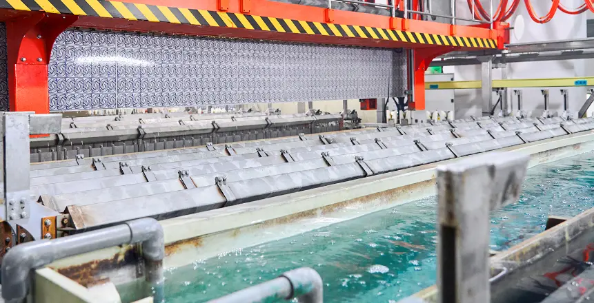
Advanced alkaline etching with photoresist tenting technology delivers industry-leading precision for high-density interconnect applications.

PCB Etching Production Line
Key Manufacturing Stages
1
Material Preparation
2
Inner Layer Processing
3
Lamination
Standard Precision Technology

Standard PCB Manufacturing

3/3mil Line Width/Spacing

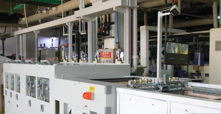
Proven acid etching with advanced dry film methodology delivers reliable precision for standard applications and power electronics.

Standard PCB Manufacturing Process
Key Manufacturing Stages
1
Material Preparation
2
Inner Layer Processing
3
Lamination
PCB Manufacturing Capability Boundaries

PCB Manufacturing Capability Boundaries

Use these values for initial screening. Final capability is confirmed against the complete material, stackup, geometry, finish, tolerance, and test combination.

FeatureDesign ScreeningAdvanced Review EnvelopeHilPCB Capability
Min. Line Width/Spacing3/3mil (75/75μm)2/2mil (50/50μm)2/2mil (50/50μm)
Max. LayersDefined by stackup and fabrication drawingAdvanced review envelope: 60+ layersUp to 64 layers (stackup confirmed during RFQ review)
Board Thickness Range (mm)Defined by pressed construction and drawingAdvanced review envelope: 0.2-10.0 mmConfirmed by HilPCB material and stackup review
Min. Hole Size (mm)Drill window confirmed from thickness and aspect ratioMicrovia, blind/buried via and backdrill reviewed by structureConfirmed by HilPCB drill-file review
Copper Weight (oz)Defined by current, temperature rise and finished copperLow-profile or heavy copper reviewed against loss and thermal designUp to 20oz (finished copper and construction confirmed during RFQ review)
Impedance ControlTarget and tolerance supplied with the RFQAdvanced review envelope: ±5% impedance couponConfirmed by HilPCB impedance table, coupon and test method
Standard Lead Time (Days)Confirmed at quotationMaterial, process, quantity and test scope affect schedule24-hour expedite for eligible builds, confirmed at quotation
Quality Certifications & Supported Standards

Quality Certifications & Supported Standards

Our certified quality systems support controlled PCB fabrication. Product standards, acceptance criteria, test methods, and documentation are confirmed for each order.

🏆

ISO 9001:2015

International quality management system certification ensuring continuous improvement and consistent manufacturing excellence.

🏥

ISO 13485:2016

Medical device quality management certification covering healthcare and life sciences electronics production.

🚗

IATF 16949:2016

Automotive industry quality management standard for safety-critical and high-reliability electronics manufacturing.

🚀

AS9100D

Aerospace and defense quality management certification for mission-critical aviation and space applications.

⭐

IPC-A-610 Class 3

Highest reliability acceptance standard for electronic assemblies in space, military, and medical devices.

🌱

RoHS Compliance

Restriction of Hazardous Substances controls with order-specific compliance documentation.

🛡️

UL Certification

Underwriters Laboratories safety certification with full material traceability and registered E-file.

🌍

REACH Compliance

European Union REACH controls with supporting material and compliance documentation.

📐

IPC-6012 Class 3

Rigid PCB qualification and performance specification for high-reliability applications.

🔧

J-STD-001

Requirements for soldered electrical and electronic assemblies with the highest workmanship standards.

Send a Quote-Ready Manufacturing Package

Our engineering team will review manufacturability, stackup, materials, testing, documentation, quantity, and delivery requirements before production release.

Frequently Asked Questions

What is the lead time for PCB manufacturing?
Standard lead time is 5-7 working days for most PCB orders, with 24-hour expedite available for eligible builds. The confirmed schedule is included in the quotation after engineering review of the stackup, materials, quantity, and test scope.
What is your minimum order quantity?
We support prototype, NPI, and production orders. The practical order quantity is confirmed during quotation based on the board construction and panel plan.
What materials do you support?
We support various materials including FR4, Rogers, Polyimide, Aluminum, Ceramic, and other specialty materials for high-frequency, high-temperature, and high-reliability applications.