In the world of electricity, few principles are as foundational and ubiquitous as Ohm's Law. Published in 1827 by German physicist Georg Simon Ohm, this elegant law provides a simple yet powerful description of the relationship between voltage, current, and resistance. It is the essential starting point for circuit analysis and the silent rule governing everything from the smartphone in your pocket to the power grid that spans nations.
This comprehensive guide delves into every facet of Ohm's Law-from its core principles and mathematical expressions to its real-world applications and crucial limitations.
1. The Core Concepts: A Simple Analogy
To truly grasp Ohm's Law, it helps to visualize electricity as water flowing through a pipe.
Voltage (V): Imagine voltage as the water pressure applied by a pump. It is the electrical potential difference that "pushes" the charge through the circuit. It is measured in Volts (V). Higher pressure leads to stronger flow.
Current (I): Current is the rate of water flow-how much water passes a point per second. It is the flow of electric charge. It is measured in Amperes (A).
Resistance (R): Resistance is a constriction or narrowing of the pipe. It is the opposition to the flow of current. It is measured in Ohms (Ω). A narrower pipe restricts the flow, even if the pressure is high.
Ohm's Law mathematically defines how these three quantities interact: the flow (current) you get depends on the pressure (voltage) you apply and the restriction (resistance) in the path.
2. The Mathematical Foundation
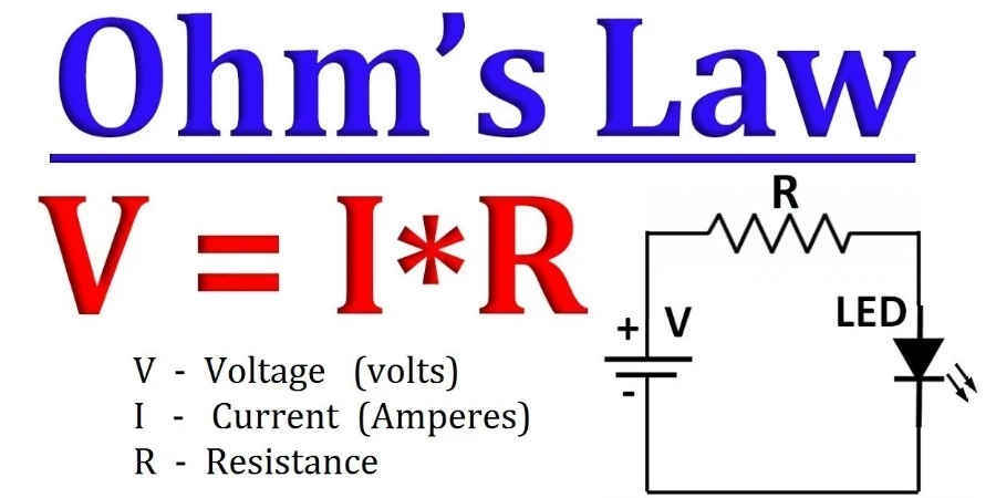
Ohm's Law is famously expressed in a simple equation:
V = I × R
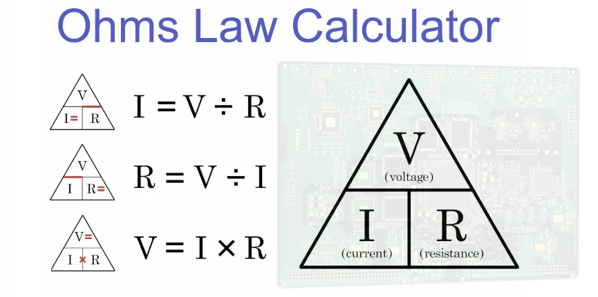
This formula states that the voltage across a conductor is equal to the current flowing through it multiplied by its resistance. This relationship can be algebraically rearranged to solve for any of the three variables, often visualized using the "Ohm's Law Triangle."
| To Find | Formula | Description |
|---|---|---|
| Voltage (V) | V = I × R |
Calculates voltage when current and resistance are known. |
| Current (I) | I = V / R |
Calculates current when voltage and resistance are known. |
| Resistance (R) | R = V / I |
Calculates resistance when voltage and current are known. |
These three expressions are the cornerstones of basic circuit analysis.
3. Visualizing Ohm's Law: The I-V Curve
When the relationship between voltage and current for a component is plotted on a graph, it's called an I-V (Current-Voltage) curve.
- For materials that strictly obey Ohm's Law, this graph is a perfectly straight line passing through the origin (0,0). This linearity indicates that the resistance is constant. Doubling the voltage will precisely double the current.
- The slope of the line is significant. On a graph with current (I) on the y-axis and voltage (V) on the x-axis, the slope is equal to
1/R. A steeper slope means lower resistance, while a shallower slope means higher resistance.
4. Ohmic vs. Non-Ohmic Devices
A crucial distinction in electronics is whether a component follows Ohm's Law.
Ohmic Devices (The Rule Followers) These devices have a constant resistance over a wide range of voltages, as long as the temperature remains stable. Their I-V graph is a straight line.
- Examples: Standard resistors, metallic conductors (copper, aluminum), and heating elements.
Non-Ohmic Devices (The Rule Breakers) These devices have a resistance that changes as the voltage or current varies. Their I-V graph is a curve, not a straight line. Ohm's Law cannot be directly applied to them in its simple form.
- Examples:
- Diodes & LEDs: These semiconductor devices allow current to flow easily in one direction but block it almost completely in the other. Their resistance is highly dependent on the voltage.
- Transistors: The resistance across a transistor is actively controlled by a third terminal, forming the basis of all modern electronics.
- Incandescent Bulbs: The tungsten filament's resistance increases dramatically as it heats up to thousands of degrees, causing its I-V graph to curve.
5. The Physics of Resistance
The resistance of a material is not an arbitrary value. It is determined by its physical properties according to the formula:
R = ρ * (L / A)
- ρ (Resistivity): An intrinsic property of the material. Copper has very low resistivity, making it an excellent conductor. Rubber has extremely high resistivity, making it an insulator.
- L (Length): Resistance is directly proportional to the conductor's length. A longer wire has more resistance.
- A (Cross-Sectional Area): Resistance is inversely proportional to the area. A thicker wire provides more pathways for electrons and thus has lower resistance.
Additionally, temperature plays a vital role. For most metals, resistance increases as temperature rises because increased atomic vibrations impede the flow of electrons.
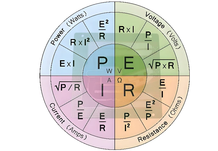
6. Power Dissipation and Joule's Law
An important consequence of resistance is energy loss, typically in the form of heat. The rate at which energy is converted is called power (P), measured in Watts (W).
The fundamental formula for electric power is:
P = V × I
By combining this with Ohm's Law, we derive two other essential power formulas:
P = I² × R(Useful for calculating power loss when current is known)P = V² / R(Useful for calculating power when voltage is known)
These are critical for tasks like selecting a resistor with an adequate power rating so it doesn't overheat and burn out.
7. Beyond DC: Ohm's Law in AC Circuits
In Direct Current (DC) circuits, current flows in one direction. In Alternating Current (AC) circuits, the current rapidly changes direction. This introduces complexity from components like capacitors and inductors, which also oppose current flow in a frequency-dependent manner. This opposition is called reactance (X).
In AC circuits, the total opposition to current-a combination of resistance and reactance-is called Impedance (Z). Like resistance, it is measured in Ohms.
For AC circuits, Ohm's Law evolves into its generalized form:
V = I × Z
This shows the adaptability of the law's core concept: the relationship between push (voltage), flow (current), and total opposition (impedance) remains constant in form.
8. Key Applications of Ohm's Law
- Circuit Design: Calculating the correct resistor value to limit current for an LED, set a voltage level, or configure a sensor.
- Fault Diagnosis: Technicians measure voltage and current to calculate resistance, quickly identifying short circuits (near-zero resistance) or open circuits (infinite resistance).
- Electrical Safety: Fuses and circuit breakers are designed based on Ohm's Law. A fuse has a low-resistance wire that melts and breaks the circuit if the current (
I = V/R) exceeds a safe level. - Power Systems: Analyzing voltage drops and power losses across long transmission lines.
9. When Does Ohm's Law Not Apply? (Its Limitations)
Ohm's Law is a model, not a universal law of nature. It is crucial to know its limits:
- It is not for non-ohmic devices: It fails for semiconductors like diodes, LEDs, and transistors.
- It assumes constant temperature: In devices where temperature changes significantly with current (like a light bulb), the law becomes inaccurate.
- It is a macroscopic model: It describes the bulk behavior of materials but doesn't apply at atomic scales or under extreme conditions like plasma or superconductivity.
Conclusion
Despite being nearly two centuries old, Ohm's Law remains the first principle taught to aspiring electricians and engineers-and for good reason. It provides an intuitive and reliable framework for understanding and manipulating electricity. By defining the fundamental interplay of voltage, current, and resistance, V = I × R serves as the indispensable key that unlocks the door to the vast and complex world of electronics.