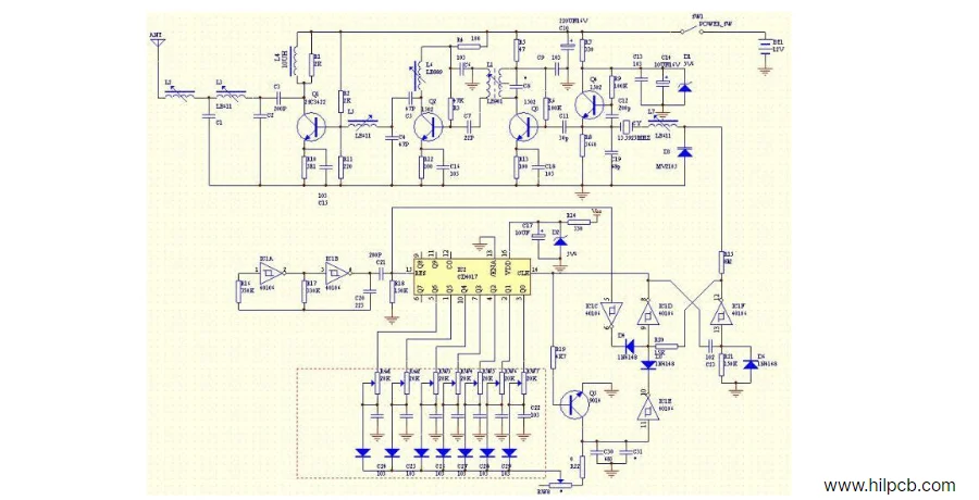
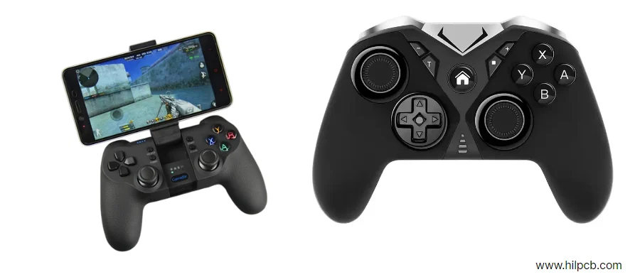
Remote control cars have captivated people for generations, combining the thrill of speed with the elegance of mechanics and electronics. At the heart of every RC car lies an invisible system-a remote control circuit-that translates your hand movements into the precise actions of the vehicle.
Understanding how this circuit works not only satisfies curiosity but also reveals the careful balance of power, control, and communication that defines modern robotics and automation systems.
1. The Concept of a Remote Control Circuit
A remote control circuit is an electronic system that allows you to command a device wirelessly. While the concept is simple-send a signal from one unit, and another responds-the process involves a complex, real-time sequence of encoding, transmitting, receiving, and decoding information.
Early RC toys used wires or ultrasonic sound. Later, infrared (IR) systems emerged, relying on light pulses that required a direct line of sight. The modern standard, however, is radio frequency (RF) communication, specifically 2.4 GHz spread-spectrum signals. This technology, also used in drones, wireless keyboards, and Wi-Fi routers, allows dozens of vehicles to operate simultaneously without interference.
2. The Basic Working Principle
Every RC system has two fundamental parts: a transmitter in your hand and a receiver inside the car.
When you move a joystick, the transmitter converts that physical movement into an electrical signal. An internal microcontroller digitizes this signal into a unique code. This code is then modulated onto radio waves and broadcasted by the antenna.
On the car, an antenna picks up these waves. The receiver’s circuit demodulates the signal, decodes it back into electrical commands, and instantly forwards those commands to the motor driver, the speed controller, and the steering servo. This entire process happens in milliseconds, creating the illusion of instantaneous response.
3. Key Electronic Components in Remote Control Car PCB Design
Modern remote control circuits are far more advanced than traditional RC systems. They now combine AI processors, digital telemetry, smart transmitters, and real-time video links, all interconnected through compact, high-density PCB designs.
Core Functional Modules
- Smart Transmitter: Today’s transmitters feature color touchscreens, customizable controls, and smartphone connectivity for FPV or telemetry display. Their PCBs integrate MCU/AI SoC, RF module, and display driver, with isolated grounds and controlled-impedance routing to maintain clean 2.4/5.8 GHz signals.
- AI Receiver and Control Hub: Modern receivers handle not just decoding, but also AI-assisted path tracking, obstacle avoidance, and autonomous driving. Multi-layer PCBs connect the receiver to ESCs, sensors, and GPS via CAN, UART, or Ethernet buses, ensuring low-latency communication and stable data flow.
- Electronic Speed Controller (ESC): Digital ESCs include real-time current sensing, temperature feedback, and firmware-tunable throttle curves. Using thick copper layers and thermal vias, the ESC PCB safely manages current surges over 100 A while minimizing EMI and heat buildup.
- Motor, Servo, and Power Section: Brushless motors pair with smart drivers using current feedback loops for smoother torque control. Servos now run on digital serial buses, improving synchronization and accuracy. The power board integrates Li-ion BMS, reverse-polarity protection, and USB-C PD 3.1 charging.
- Sensors and Autonomous Modules: Modern systems fuse GPS, IMU, ultrasonic, and vision sensors for AI-based navigation. These often reside on separate rigid-flex PCBs linked via high-speed connectors to reduce interference.
- System PCB Integration: Multi-zone PCBs isolate logic, RF, and high-power areas for reliability. Using 4-6 layer boards with internal copper planes and EMI shielding, designers achieve strong signal integrity and stable power delivery under dynamic loads.
Reliable Performance Through Intelligent PCB Architecture
Through advanced layout partitioning, high-frequency routing, and thermal management, remote control circuits now support real-time telemetry, adaptive control, and semi-autonomous operation. These compact PCBs unite AI computing, RF communication, and power electronics-enabling remote systems that are smarter, faster, and more connected than ever before.

4. The Communication Process Explained
The communication between the transmitter and receiver is a rapid, multi-stage process. The transmitter's microcontroller samples the analog joystick positions, converts them into digital values, and packages them into data frames. These frames are broadcasted as radio bursts thousands of times per second.
The receiver captures these bursts, checks them for errors, and unpacks the data. Each value corresponds to a control channel (throttle, steering, etc.). The receiver then generates the appropriate PWM signals for the ESC and servo. Modern 2.4 GHz systems use frequency-hopping spread spectrum (FHSS) technology, constantly changing frequencies to avoid interference and maintain a robust link, which is why they are far more reliable than older analog systems.
5. Building Your Own Remote Control Car Circuit
Constructing a basic RC circuit is an excellent educational project. For short-range models, infrared (IR) systems can work, but for practical control, 2.4 GHz radio modules like the nRF24L01 or ESP32-based Wi-Fi/Bluetooth solutions are far superior.
A typical DIY receiver circuit would include:
- A regulated power supply (a 5V BEC).
- An RF module for data reception.
- A microcontroller (like an Arduino or ESP32) for decoding signals.
- A motor driver or ESC to control the main motor.
- An interface to send PWM signals to the steering servo.
After assembly, test each subsystem independently. Ensure the transmitter and receiver are paired, the receiver outputs correct PWM signals, and the motor responds smoothly to throttle inputs before mounting the circuit in the car chassis.

6. Modern Improvements and Advanced Features
Today’s RC cars are miniature marvels of technology. Many include telemetry, which sends real-time data like speed, motor temperature, and battery voltage back to the controller's screen. Others use sophisticated ESCs that offer programmable features like adjustable braking force and throttle curves.
Some systems now integrate gyroscopic sensors (e.g., AVC - Active Vehicle Control) to automatically correct steering and prevent spin-outs, while wireless standards continue to advance, allowing for control via smartphone apps over Bluetooth or Wi-Fi.
7. Power and Safety Considerations
High-performance RC cars draw significant current, making safety crucial. Always use wires thick enough for the load and ensure the ESC and battery ratings are compatible. Li-Po batteries, in particular, require a dedicated balance charger and must be handled carefully to prevent damage.
When designing a PCB, best practice dictates separating the high-current motor ground from the sensitive signal ground and placing decoupling capacitors near all ICs. Proper layout and grounding are what separate a responsive RC car from an erratic one.
8. Conclusion
Remote control car circuits, while seemingly simple, are elegant, self-contained electronic systems. On a few square inches of PCB, a world of physics, coding, and electrical engineering cooperates to turn invisible radio waves into tangible motion.
From early wired toys to today’s intelligent 2.4 GHz models, RC technology continues to evolve. The next generation will undoubtedly feature greater autonomy, sensor feedback, and even AI-assisted control. But the foundation will remain the same: a transmitter, a receiver, and the beautiful complexity of a circuit that translates human intent into action.
