Schematic diagrams are the blueprint of every electronic device, from everyday consumer gadgets to complex systems like satellites and medical equipment. At the core of these diagrams are schematic symbols, which serve as the standardized language that engineers, designers, and hobbyists use to communicate the functionality and connections of electrical components.
In this guide, we will dive into the fundamentals of schematic symbols, explain their significance, and provide you with the tools and best practices to read and draw circuit diagrams like a professional.
What Are Schematic Symbols?
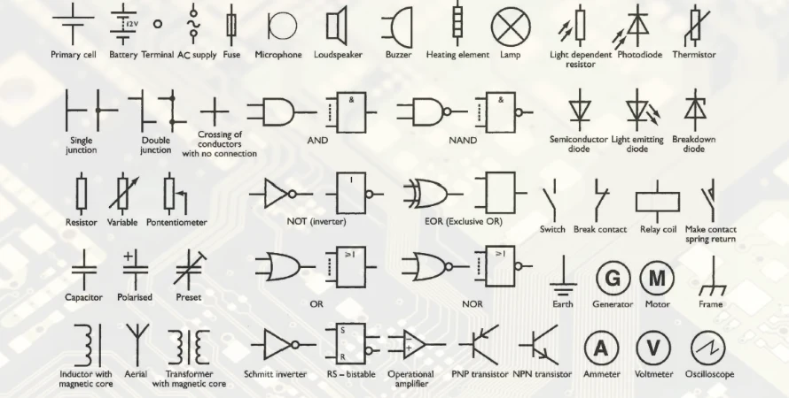
Schematic symbols are standardized graphical representations used to represent electrical and electronic components in a circuit diagram. Instead of drawing the actual physical appearance of components, schematic symbols abstract these elements into simple shapes, making it easier for engineers to design, share, and understand circuits across teams and industries.
These symbols follow specific standards, including:
- IEC 60617 - International standard for electrical symbols.
- IEEE 315 - U.S. standard that defines schematic symbols.
- ANSI Y32.2 - North American adaptation for diagramming electrical systems.
By using consistent schematic symbols, engineers can create diagrams that are both universally readable and easily manufacturable.
Key Categories of Schematic Symbols
While there are countless symbols used in circuit diagrams, the most common ones fall into the following categories:
Passive Components
These symbols represent basic components that don’t require an external power source to operate.
- Resistors - Represented by a zig-zag line or rectangle, resistors limit the flow of current.
- Capacitors - Two parallel lines represent capacitors; they store and release energy.
- Inductors - Typically depicted as coiled lines, inductors store energy in magnetic fields.
Active Components
These symbols are for components that require external power to function or amplify signals.
- Transistors - A crucial part of amplifying circuits. NPN and PNP transistor symbols include three terminals: Base (B), Collector (C), and Emitter (E).
- Diodes & LEDs - Diodes allow current to flow in one direction only, while LEDs emit light when current flows through them.
Power & Control Elements
These symbols are used to manage the power in the circuit or provide control signals.
- Batteries - Represented by alternating long and short parallel lines.
- Switches - Represent the opening or closing of a circuit.
- Ground - Depicted with three horizontal lines, grounding is essential for safety and functionality in electrical designs.
How to Read and Interpret Schematic Diagrams
Reading a schematic symbol is more than memorizing shapes; it’s about understanding how components interact. Here are some expert tips to help you effectively read schematics:
- Understand the Flow: Follow the signal or current path logically, from the input to the output. Power typically comes from the top, and ground is at the bottom.
- Component Designators: Identify reference designators like R1 (resistor), C1 (capacitor), Q1 (transistor), U1 (IC). Each of these designates a unique part of the circuit.
- Recognize Key Components: Look for the most important symbols first (resistors, capacitors, ICs). If you understand these, the rest of the circuit will make sense.
- Observe Polarities and Connections: Many components, like capacitors, diodes, and LEDs, have specific polarity. Be sure to look for the correct orientation and connections.
- Trace the Power and Signal Paths: Follow how current or signals flow through the circuit. Visualize voltages and waveforms as they pass through various components.
Pro Tip: When analyzing a schematic, think in terms of voltage nodes and current paths, not just individual components.
Best Practices for Drawing Schematic Diagrams
A well-drawn schematic is essential for clear communication, whether it’s for a personal project, professional work, or a team-based collaboration. Below are best practices to help you draw clear and precise circuit diagrams:
Plan Your Layout
- Arrange components from left (input) to right (output).
- Place power rails at the top and ground at the bottom to maintain consistency.
- Group related components logically to create clean, understandable sections (e.g., signal input stage, amplification stage, output stage).
Use Standard Symbols Consistently
- Stick to industry-standard symbols like those in IEC or IEEE.
- Consistency is key-don't mix different symbol styles.
Label Everything Clearly
- Assign unique reference designators (e.g., R1, C2) to components.
- Clearly mark the values and tolerances of components (e.g., 10kΩ resistor, 100μF capacitor).
- Use net labels like VCC, GND, IN, OUT for power and signal connections.
Design for Manufacturing
- Ensure all components are connected to valid nets (no floating pins).
- Perform Electrical Rule Checks (ERC) and Design Rule Checks (DRC) to catch any mistakes before finalizing the design.
Use Professional CAD Tools
- Altium Designer, KiCad, OrCAD, and Eagle are popular tools that offer symbol libraries and automated validation to help create professional circuit diagrams quickly.
Conclusion
Schematic symbols are not just symbols-they are the building blocks of every successful electronic design. Understanding them is critical to creating clear, readable, and manufacturable circuit diagrams.
By following industry standards, using the right tools, and practicing good drawing habits, you’ll ensure that your designs are both professional and easy to interpret. Whether you are a student, hobbyist, or seasoned engineer, mastering schematic symbols is an essential skill that will make your electronic designs faster, clearer, and more effective.
Frequently Asked Questions (FAQ)
Q1: What are the most essential schematic symbols to know?
A: The most important symbols to memorize include resistors, capacitors, diodes, transistors, and power components.
Q2: How can I quickly identify the function of a symbol?
A: Focus on the shape and annotation (value, polarity). For example, arrows in a diode symbol show the direction of current flow.
Q3: Should I draw schematics by hand or use CAD software?
A: For professional designs, CAD software (like Altium or KiCad) is recommended for accuracy and ease of editing. For personal or learning purposes, hand-drawing is fine.