In electronics and printed circuit board design, accurately converting watts (W) to amps (A) is essential. Whether you're working on a prototype or full-scale production, understanding how much current your circuit draws impacts trace widths, component ratings, thermal performance, and the entire manufacturing process. A reliable watts to amps calculator or conversion method is indispensable for engineers and manufacturers alike.
At a foundational level, the formula and its implications guide critical decisions in board design and fabrication. For example, when performing full PCB manufacturing and assembly through a provider like HILPCB, these calculations are part of ensuring your board meets performance and reliability standards. Additionally, using circuit simulation tools - such as HILPCB’s online circuit simulator - can help validate power consumption and current draw before moving into manufacturing. The following sections dive deeply into the formula, how it applies in PCB and electronics contexts, and provide best practices to support production-ready data.
Understanding Watts, Amps and Their Role in PCB Design
What Watts and Amps Represent
- Watts (W): A measure of power - the rate at which electrical energy is consumed or produced.
- Amps (A): A measure of current - the flow of electric charge in a circuit.
In PCB design and electronics manufacturing, translating power requirements to current values allows you to size traces, select components and plan power delivery properly.
Why Conversion Matters in PCB & Assembly
Accurate current calculation influences:
- Trace widths, copper weight and thermal considerations.
- Power supply selection and distribution on the board.
- Design for manufacturability (DFM) and design for testability (DFT) in a production environment.
When you plan to have your board fabricated and assembled-turning your design into reality at a manufacturer like HILPCB-you’ll benefit from having these calculations well established early on.
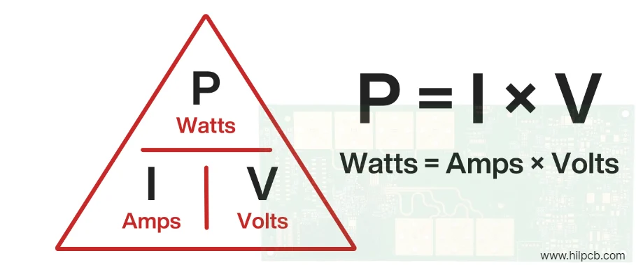
Watts to Amps Conversion Formula
The basic relationship is as follows: Current (A) = Power (W) ÷ Voltage (V)
Example for DC or Resistive Load
If a board consumes 120 W at 12 V, then: Current (A) = 120 W ÷ 12 V = 10 A
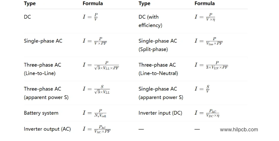
Considerations for AC & Complex Loads
For AC circuits, especially with reactive components, you may need to consider the power factor (PF): Current (A) = Power (W) ÷ (Voltage (V) × Power Factor (PF))
For three-phase systems: Current (A) = Power (W) ÷ (√3 × Line Voltage (V_LL) × Power Factor (PF))
These advanced formulas are less common in typical PCB work but are important in power electronics or large-scale systems.
Practical Table & Calculator for Conversion
| Power (W) | Voltage (V) | Current (A) | Notes |
|---|---|---|---|
| 50 | 12 | 4.17 | Low power board example |
| 100 | 24 | 4.17 | Higher voltage case |
| 200 | 24 | 8.33 | Power supply example |
| 500 | 120 | 4.17 | Higher voltage, lower current |
| 1000 | 12 | 83.33 | Example of large current draw |
You can turn these calculations into a simple “watts to amps calculator” in spreadsheets or use online tools to streamline.
How This Affects PCB Manufacturing & Design
Trace Width and Copper Weight Selection
The calculated current determines how wide a copper trace must be to safely carry the load without overheating or excessive voltage drop. The widely-used standards (such as IPC-2221) guide trace width based on current-carrying capacity and ambient conditions.
Component and Connector Ratings
If your current calculation shows 10 A drawn from a regulator or connector, you must select components that safely handle that current plus a safety margin-for reliability and manufacturability.
Power Distribution on the Board
In PCB layout, power planes, vias, thermal reliefs and decoupling must account for the designated current paths. For a production run at a manufacturing partner like HILPCB, defining these early reduces iteration and supports efficient assembly.
Validating with Simulation & Prototyping
Before sending to fabrication or assembly, it’s wise to simulate your power distribution and current flows using a circuit simulator. Using HILPCB’s circuit simulator tool can help ensure your design is electrically sound, so when you go into full board production, the specification is robust and well-defined.
Common Mistakes and How to Avoid Them
- Ignoring the voltage: Calculating amps without knowing the exact voltage will produce incorrect results.
- Assuming PF = 1 in AC circuits: Leads to underestimated current and possible trace overheating.
- Selecting too narrow traces: Causes excessive resistance, heating, and potential failure in assembly or in-field.
- Failing to include safety margin: Components and traces should be rated above the calculated current.
- Not validating via simulation or test: Skipping simulation may result in overlooked hotspots or unexpected currents, especially in high-speed or high-power PCBs.
Why Accurate Conversion Matters for Manufacture & Assembly
Accurately converting watts to amps is more than just a theoretical exercise-it is critical to the manufacturability, reliability, and overall cost of your project. Without proper electrical verification, focusing solely on surface-level design features can lead to serious issues such as board failures, design revisions, and unexpected increases in production costs. Ensuring that electrical parameters are accurately accounted for throughout the design process helps avoid these pitfalls.
A well-defined and rigorous process, from simulation through to prototyping, not only enhances design quality but also streamlines the production transition. This includes both bare board fabrication and full assembly. At HILPCB, we take a comprehensive approach by integrating these crucial steps into our service offering. This ensures that the final product is not just a visually accurate design, but a fully manufacturable and reliable PCB ready for real-world application. Our focus on electrical validation means that you’ll avoid costly delays and revisions, delivering a more efficient and cost-effective solution.
FAQ
Q1: Why must I convert watts to amps in PCB design?
A1: Because the current (amps) dictates trace widths, component ratings and thermal design; without this conversion, the board may fail or underperform.
Q2: What voltage should I use in the formula?
A2: Use the voltage at which your circuit will operate. For example, if your system uses 5 V logic but also a 12 V rail, separate the loads accordingly.
Q3: Does the formula change for AC or three-phase systems?
A3: Yes. AC circuits may need a power factor adjustment; three-phase requires √3 factor in the denominator.
Q4: How do I choose trace width after calculating current?
A4: Use IPC-2221 or similar trace-width tables based on current, copper thickness, temperature rise, and board class.
Q5: Can I rely solely on a watts to amps calculator online?
A5: They’re helpful, but you need to consider board-specific factors: voltage drops, temperature, trace length, and manufacturing tolerances. Combine calculation with simulation and review.