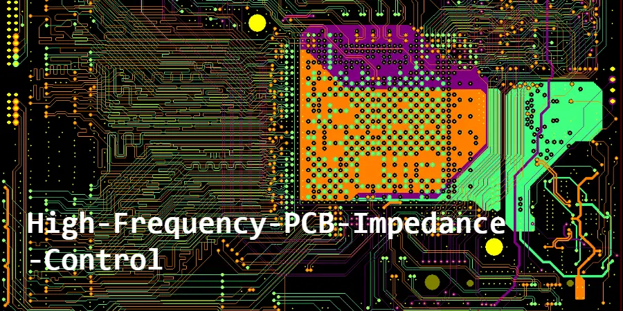
Impedance control is the foundation of successful high-frequency PCB design. As operating frequencies exceed 1 GHz and data rates surpass 10 Gbps, maintaining precise impedance control determines whether your design functions reliably or fails completely. This guide provides practical solutions for achieving and maintaining impedance control from design through manufacturing.
What is High-frequency PCB Impedance Control and Why It Matters
High-frequency PCB impedance control refers to maintaining the characteristic impedance of transmission lines within specified tolerances. At frequencies above 100 MHz, PCB traces behave as transmission lines with specific impedance determined by geometry and materials.
Critical Impact on System Performance:
When impedance mismatches occur, signal reflections cause:
- Bit errors in digital systems (>10^-12 BER)
- Reduced power transfer in RF circuits (>3dB loss)
- Standing waves that damage amplifiers
- Eye diagram closure beyond specifications
Industry Standard Impedance Values:
- 50Ω: RF/microwave applications
- 75Ω: Video systems
- 90Ω: USB differential pairs
- 100Ω: Ethernet, PCIe differential
Most high-speed PCB designs require ±5-10% tolerance, while critical RF applications demand ±3% or better.
How to Calculate and Design for Impedance Control
Microstrip Impedance Calculation Methods
The characteristic impedance of microstrip depends on trace width, substrate height, and dielectric constant:
Simplified Formula: Z₀ = 87/√(εr + 1.41) × ln(5.98h/(0.8w + t))
Practical Example for 50Ω:
- Material: Rogers RO4003C (εr = 3.38)
- Substrate: 0.508mm (20 mil)
- Calculated width: 1.11mm
- Tolerance achieved: ±2Ω
Key Design Factors:
- Trace Width Control: ±0.025mm affects impedance by ±2Ω
- Dielectric Thickness: ±10% variation causes ±5% impedance shift
- Solder Mask Impact: Adds 2-3Ω to microstrip impedance
- Surface Roughness: Increases impedance 1-2Ω at high frequencies
Stripline and Differential Pair Design
Stripline Configuration Benefits:
- Better field containment
- No frequency dispersion
- Superior crosstalk isolation
- Consistent impedance
Differential Impedance Requirements:
- Target: 90-100Ω typical
- Intra-pair matching: <0.025mm
- Coupling factor: 0.15-0.25
- Length matching: Critical for >5 Gbps
Best Practices for Maintaining Impedance Control
Stack-up Design for Optimal Performance
A well-designed stack-up ensures consistent impedance across all layers:
6-Layer Controlled Impedance Stack-up:
| Layer | Function | Material | Impedance Target |
|---|---|---|---|
| L1 | Signal | 0.5 oz Cu | 50Ω ±5% |
| L2 | Ground | 1 oz Cu | Reference |
| L3-4 | Signal | 0.5 oz Cu | 50Ω stripline |
| L5 | Power | 1 oz Cu | - |
| L6 | Signal | 0.5 oz Cu | 50Ω ±5% |
Critical Stack-up Rules:
- Maintain continuous reference planes
- Use symmetric construction
- Match material CTE values
- Consider manufacturability limits
Material Selection Impact on Impedance Stability
Material properties directly affect impedance control capability:
Material Comparison for Impedance Control:
| Material | Dk Tolerance | Stability | Cost | Best For |
|---|---|---|---|---|
| FR4 | ±10% | Poor | 1× | <2 GHz |
| Rogers 4350B | ±0.05 | Good | 4× | <20 GHz |
| Rogers 3003 | ±0.02 | Excellent | 8× | >20 GHz |
| PTFE | ±0.02 | Best | 10× | mmWave |
Selection Criteria:
- Operating frequency range
- Temperature stability requirements
- Cost constraints
- Manufacturing compatibility
Common Impedance Control Problems and Solutions
Manufacturing Variations and Compensation
Understanding manufacturing tolerances helps design robust impedance-controlled circuits:
Typical Process Variations:
- Etching: ±20% of copper thickness
- Plating: ±25μm variation
- Lamination: ±10% thickness change
- Registration: ±75μm between layers
Compensation Strategies:
- Pre-compensation in Design: Account for etch factor
- Process Control: Statistical monitoring (Cpk >1.33)
- 100% Testing: TDR verification on critical designs
- Tolerance Budgeting: Design for worst-case stackup
Via Transitions and Discontinuities
Vias represent major impedance discontinuities requiring careful optimization:
Via Impact on Impedance:
- Standard via: 25-35Ω (vs 50Ω trace)
- Creates 10-15% reflection coefficient
- Stub resonances above 5 GHz
Optimization Techniques:
- Optimize antipad size (typically via + 0.25mm)
- Add ground vias within 1mm
- Implement backdrilling for stubs >1mm
- Use HDI PCB microvias above 20 GHz
Testing and Verification Methods
TDR Testing for Production Verification
Time Domain Reflectometry provides comprehensive impedance verification:
TDR Requirements:
- Rise time: <35ps for accuracy
- Resolution: ±1Ω typical
- Spatial resolution: 1mm
Interpreting Results:
- Flat trace: Good control
- Upward spike: High impedance/open
- Downward dip: Low impedance/short
- Oscillations: Multiple reflections
Network Analyzer Measurements
For frequencies above 10 GHz, VNA testing provides superior accuracy:
Key Measurements:
- S11: Return loss (<-15dB minimum)
- S21: Insertion loss verification
- Group delay: Phase linearity
- Smith chart: Complex impedance
Impedance Requirements for Different Applications
5G and Telecommunications
Sub-6 GHz Requirements:
- Impedance: 50Ω ±7%
- Return loss: >15dB
- Materials: Low-loss FR4 acceptable
mmWave (24-40 GHz):
- Impedance: 50Ω ±3-5%
- Return loss: >20dB
- Materials: PTFE required
- Surface roughness: <1μm critical
High-Speed Digital Interfaces
PCIe Gen 4/5:
- Differential: 85Ω ±5%
- Via stubs: Backdrilling required
- Materials: Df <0.005
DDR4/DDR5:
- Single-ended: 40Ω
- Differential DQS: 80Ω
- Length matching: ±0.1mm
Cost Optimization Strategies
Balancing Performance and Cost
Tolerance vs. Cost Trade-offs:
| Tolerance | Yield | Cost Impact | Applications |
|---|---|---|---|
| ±10% | >95% | Baseline | Consumer |
| ±7% | 90% | +15% | Industrial |
| ±5% | 85% | +30% | Telecom |
| ±3% | 75% | +50% | Military |
Cost Reduction Methods:
- Standardize trace widths
- Use common stack-ups
- Selective impedance control
- Statistical sampling vs 100% test
HILPCB’s Advantages in Impedance Control for HF PCB Manufacturing
In HF PCB manufacturing, impedance control is critical for maintaining signal integrity and ensuring reliable high-frequency performance. At HILPCB, every design undergoes a thorough impedance review during engineering, regardless of whether the customer has explicitly provided impedance specifications. When impedance-critical nets or layers are identified, we apply precise control and verification to meet the required performance targets.
- Precision Capability: For HF PCB critical nets, standard tolerance is ±3%, with tighter control available on request.
- Material Assurance: Full inventory of high-frequency laminates (Rogers, Taconic, Isola, Arlon, etc.) selected to match target Dk/Df and thickness requirements.
- Testing & Verification: 100% TDR testing on coupons for each production lot, with detailed impedance reports supplied.
- Technical Support: Free pre-build impedance calculation, HF PCB stack-up validation, and DFM optimization recommendations.
- Industry Experience: Proven success in 5G, radar, aerospace, and other high-frequency applications.
- Quality Certification: IPC Class 3 and ISO 9001 compliance for consistent quality and reliability.