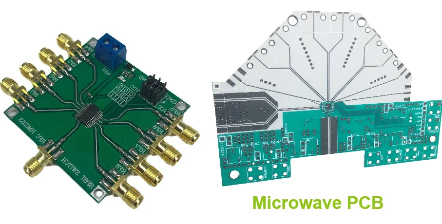
Microwave PCBs operate at frequencies where the electromagnetic wavelength becomes comparable to physical circuit dimensions. This fundamental shift changes everything about how circuits behave, forcing designers to abandon traditional approaches in favor of distributed element design techniques.
At 10 GHz, the wavelength in a typical PCB substrate is approximately 15mm. Quarter-wave sections become 3.75mm long – smaller than many surface-mount components. This scaling effect means that every PCB feature becomes part of the circuit's electrical behavior, not just a passive interconnection.
Microwave Frequency Band Applications
The microwave spectrum spans from 1 GHz to 30 GHz, encompassing numerous commercial and military applications.
L-Band (1-2 GHz)
S-Band (2-4 GHz)
C-Band (4-8 GHz)
X-Band (8-12 GHz)
Ku-Band (12-18 GHz)
K/Ka-Band (18-40 GHz)
Via resonances • Material losses
Back-drilling techniques • Low-loss substrates
Distributed Element Design in Microwave PCB
In Microwave PCB design, traditional lumped elements become ineffective when component and trace dimensions approach the wavelength. This is where distributed elements play a vital role. These elements use transmission line effects to achieve desired circuit functions. A quarter-wave transmission line acts as an impedance inverter, while half-wave sections repeat impedances, and eighth-wave sections provide specific phase shifts, ensuring optimal performance at microwave frequencies.
Coupled line structures in Microwave PCB design are key for power division, filtering, and impedance matching. By adjusting the spacing between transmission lines, engineers can control power splitting ratios and filter characteristics with precision. These structures are essential for achieving the high-performance standards required in microwave applications.
When it comes to Microwave PCB designs, stub networks replace traditional lumped inductors and capacitors. A quarter-wave short-circuited stub presents infinite impedance, while an open-circuited stub provides zero impedance, making them perfect for creating complex matching networks. As component or trace dimensions exceed one-tenth of the wavelength, distributed design techniques become necessary, ensuring designs maintain accuracy and high performance.
Material Selection for Microwave Applications
Premium Microwave Materials
Microwave applications demand materials with exceptional electrical properties and environmental stability. The choice of substrate material often determines the success or failure of the entire system.
Ultra-low loss materials like Rogers RT/duroid 5880 achieve dissipation factors below 0.001, preserving signal integrity through complex circuit networks. These PTFE-based materials excel in precision applications where signal purity is paramount.
Temperature-stable materials maintain consistent electrical properties across wide temperature ranges. The temperature coefficient of dielectric constant (TCDk) should be minimized for applications experiencing environmental temperature variations.
High-power materials must handle significant RF power levels without breakdown or excessive heating. Thermal conductivity becomes important for removing heat from high-power amplifier stages, while breakdown voltage limits the maximum power handling capability.
Manufacturing compatibility affects both cost and yield. Materials compatible with standard PCB processing techniques cost less to fabricate and achieve higher yields than exotic materials requiring specialized handling procedures.
The material selection process requires balancing electrical performance, environmental requirements, manufacturing compatibility, and cost constraints. Premium materials justify their cost in applications where performance is critical, while cost-optimized materials serve well in less demanding applications.
Power Management and Thermal Design
Microwave circuits often concentrate significant power in small areas, creating thermal management challenges that can affect both performance and reliability. Effective thermal design becomes essential for stable operation.
Power amplifier thermal management requires careful attention to heat removal paths. High-power GaN amplifiers can generate several watts per square millimeter, demanding efficient heat spreading and external cooling. Thermal vias under power devices provide conduction paths to heat-spreading layers or external heat sinks.
Temperature effects on RF performance can be significant. Dielectric constant changes with temperature affect resonant frequencies and impedance matching. Active devices show temperature-dependent gain and efficiency characteristics that must be accounted for in system design.
Thermal cycling reliability stresses solder joints and material interfaces through repeated expansion and contraction cycles. Different materials expand at different rates, creating mechanical stress that can lead to failures over time.
Design techniques for thermal management include strategic component placement, thermal via arrays, and copper heat spreading areas. Power devices should be positioned for optimal heat removal while maintaining RF performance requirements.
Processing thermal management into the RF PCB design from the beginning prevents performance problems and reliability issues.
Manufacturing and Testing Considerations
Microwave PCBs push manufacturing tolerances and testing capabilities to their limits. Success requires enhanced process controls and specialized measurement equipment.
Dimensional accuracy becomes critical as circuit dimensions approach wavelength scales. Trace width variations that would be insignificant at lower frequencies can cause meaningful impedance changes at microwave frequencies.
Via processing requires special attention to aspect ratios, plating uniformity, and stub removal. Back-drilling eliminates resonant stubs that would otherwise create performance anomalies at specific frequencies.
Surface finish selection affects both electrical performance and reliability. Smooth, consistent finishes minimize skin effect losses and provide reliable soldering surfaces for microwave components.
Testing challenges arise from the difficulty of making accurate measurements at microwave frequencies. Probe positioning, calibration stability, and measurement uncertainty become significant factors in production testing.
Comprehensive validation requires specialized test equipment and techniques designed specifically for microwave applications, as covered in our RF PCB testing guide.
Ready to tackle your most challenging microwave design requirements? Our microwave specialists combine deep theoretical knowledge with practical manufacturing experience to deliver solutions that work in production.
Microwave PCB Expertise
Advanced design and manufacturing for 1-30 GHz applications
Start Your ProjectExpert Services: RF PCB Impedance Control | High-Frequency Circuit Board | RF PCB Manufacturing