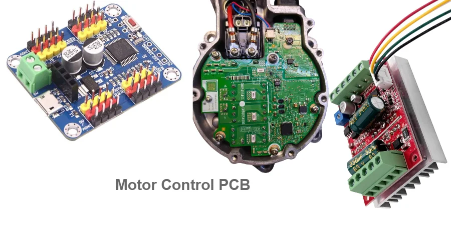
The electrification revolution is transforming industries from automotive to industrial automation, with motor control PCBs at the heart of this transformation. Whether controlling a 100W BLDC motor in a drone or managing a 100kW industrial pump, the fundamental PCB design challenges remain consistent: power handling, thermal management, and electromagnetic compatibility.
At Highleap PCB Factory (HILPCB), we've designed motor control PCBs across the entire power spectrum. This guide covers essential aspects from basic circuits to advanced thermal management techniques.
BLDC Motor Control PCB Design and Components
Brushless DC motor control requires sophisticated electronic commutation to replace mechanical brushes. The PCB design must handle three-phase power switching while providing precise timing control.
Three-Phase Inverter Bridge: The core component is the three-phase inverter bridge using six power MOSFETs or IGBTs. For low-power applications (<1kW), integrated power modules like the DRV8323 combine gate drivers and power switches. Higher power applications require discrete devices with separate gate drivers on heavy copper PCB designs.
Gate Driver Implementation: High-side gate drivers need bootstrap circuits or isolated power supplies. Modern gate driver ICs like the UCC27322 provide fast switching with integrated protection. PCB layout must minimize gate drive loop inductance to prevent oscillations and switching losses.
Current Sensing Methods: BLDC control requires current sensing for protection and control. Inline shunt resistors provide cost-effective solutions for lower currents, while Hall effect sensors offer better isolation for high-current applications requiring sufficient bandwidth for switching frequencies.
Position Sensing Integration: BLDC motors require rotor position information for proper commutation. Hall sensors provide discrete position information, while encoders enable precise control. Sensorless algorithms use back-EMF sensing to eliminate external sensors.
Control Algorithm Implementation: Modern BLDC control uses field-oriented control (FOC) on dedicated microcontrollers like the STM32G4 series, providing hardware acceleration for trigonometric functions and high-resolution PWM generation.
AC Motor Drive PCB Layout and Power Electronics
AC motor drives convert fixed-frequency AC power to variable frequency output, enabling precise speed and torque control. PCB design must handle high voltages while maintaining electrical safety and electromagnetic compatibility.
Power Stage Architecture: Three-phase AC drives include input rectification and power factor correction circuits. Active PFC using boost converters improves efficiency and reduces harmonic distortion. High-speed PCB design techniques ensure signal integrity in control circuits.
DC Bus Design: High-capacitance electrolytic capacitors store energy between rectifier and inverter sections. Film capacitors provide low-inductance high-frequency filtering. PCB design must provide low-inductance connections to minimize voltage spikes during switching transitions.
IGBT Gate Drive Circuits: AC drives typically use IGBTs for power switching due to excellent high-voltage performance. IGBT drivers require negative gate voltage for turn-off preventing parasitic turn-on. Isolated drivers prevent ground loops while providing necessary voltage levels.
Protection and Monitoring: Comprehensive protection includes overcurrent, overvoltage, and overtemperature detection. Current transformers measure AC currents while voltage dividers monitor DC bus voltage. Thermal monitoring prevents component damage during overload conditions.
DC Motor Controller PCB Circuits and H-Bridge Design
DC motor control offers simpler implementation but requires careful PCB design for optimal performance. H-bridge circuits enable bidirectional control with regenerative braking capability.
H-Bridge Configuration: Electronic H-bridges using MOSFETs provide variable speed control through PWM techniques. Integrated H-bridge ICs like the L298N simplify design for lower power applications, while discrete designs offer better performance for higher currents.
PWM Generation and Control: PWM frequency selection balances switching losses with audible noise. Higher frequencies (20kHz+) eliminate audible noise but increase switching losses. Dedicated timer peripherals in microcontrollers or specialized PWM controllers generate precise timing.
Current Limiting and Protection: DC controllers must include current limiting preventing damage during stall conditions. Current sensing using shunt resistors enables both protection and closed-loop current control with thermal protection preventing overheating.
Speed and Position Feedback: Encoder feedback enables precise speed and position control. Quadrature encoder interfaces require differential line receivers for noise immunity, with proper velocity calculation filtering to prevent noise amplification.
Thermal Management for High-Power Motor Drives
Power dissipation creates significant thermal challenges affecting both performance and reliability. Effective thermal management is crucial for achieving rated power output and component longevity.
Power Loss Analysis: Calculate losses from each component under worst-case conditions. Switching losses increase with frequency and current, while conduction losses dominate at low frequencies. Gate driver losses become significant in high-frequency applications.
Advanced PCB Thermal Design: Metal core PCB construction provides superior thermal performance for high-power applications. Thermal vias connect power components to internal copper planes, creating efficient heat dissipation paths.
Heat Sink Integration: Power levels above 30W typically require external heat sinks. PCB design must accommodate mounting while maintaining electrical isolation. Thermal interface materials improve heat transfer efficiency between components and cooling systems.
Thermal Monitoring: Integrated temperature sensors monitor critical temperatures enabling thermal protection algorithms. NTC thermistors provide cost-effective sensing, while digital sensors offer better accuracy and communication interfaces.
EMI Control and EMC Compliance for Motor Drives
Motor control PCBs generate significant electromagnetic interference due to high-speed switching. EMI control must be designed from the beginning rather than added afterward.
EMI Source Management: Switching devices create both common-mode and differential-mode noise. Common-mode currents flow through parasitic capacitances creating electromagnetic emissions, while differential-mode currents in motor cables generate conducted emissions.
PCB Layout Optimization: Minimize switching loop areas by placing decoupling capacitors close to power devices. Use ground planes providing low-impedance return paths. Separate analog and digital circuits preventing noise coupling between sensitive and noisy sections.
Filtering Strategies: Multi-stage input filters address both common-mode and differential-mode noise. Common-mode chokes and Y-capacitors attenuate common-mode noise, while differential inductors and X-capacitors address differential-mode emissions.
Grounding and Shielding: Single-point grounding prevents ground loops while maintaining isolation. Chassis grounding provides electromagnetic shielding ensuring electrical safety. PCB-to-chassis bonding requires careful design avoiding noise coupling paths.
Motor Control PCB Manufacturing and Assembly
Motor control PCBs require specialized manufacturing techniques handling high currents and voltages while maintaining quality and reliability. Assembly processes must accommodate large power components ensuring thermal management.
Manufacturing Considerations: Multi-layer designs provide dedicated power and ground planes for clean distribution. High-current traces require wide copper widths or multiple parallel layers. Via current capacity must be calculated based on size and quantity for high-current connections.
Component Selection: Power devices must be rated for worst-case conditions with appropriate safety margins. Gate drivers require adequate drive strength for intended switching frequencies. Passive components must handle ripple currents and voltages at operating frequencies.
Assembly and Quality Control: Large power components require specialized reflow profiles preventing thermal damage. In-circuit testing verifies component placement and connectivity. Functional testing under load validates performance across operating ranges.
Our turnkey assembly services provide complete manufacturing solutions from PCB fabrication through final testing, ensuring reliable motor control systems. Design files can be verified using our Gerber viewer before production.
Frequently Asked Questions
Q: What's the difference between BLDC and AC motor control PCBs? BLDC controllers use six-step or sinusoidal commutation at lower voltages, while AC drives handle higher voltages with more complex algorithms and larger filtering components.
Q: How do you minimize EMI in motor control applications? Proper PCB layout minimizing loop areas, multi-stage filtering, correct grounding techniques, and shielded enclosures for high-power applications.
Q: What thermal management works best for high-power drives? Metal core PCBs, thermal vias, external heat sinks, and forced air cooling. Thermal monitoring enables protection and performance optimization.
Q: How do you select power devices for motor control? Consider voltage/current ratings with safety margins, switching characteristics for intended frequency, thermal resistance for expected power dissipation, and package options for thermal management.
Q: What testing is required for motor control PCB validation? Electrical verification, thermal characterization, EMC compliance testing, and motor load testing across full operating ranges with environmental validation under industrial conditions.