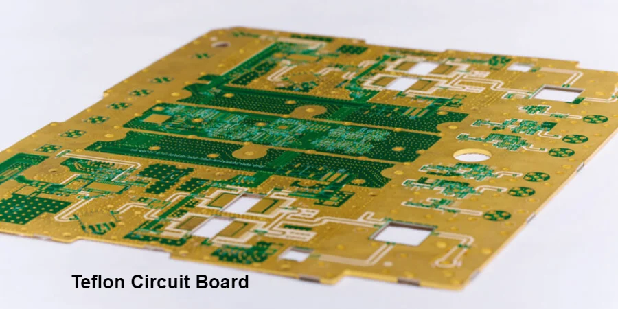
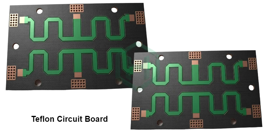
In the demanding world of RF and microwave engineering, signal integrity is the ultimate measure of success. Teflon circuit boards-built on high-performance PTFE (Polytetrafluoroethylene)-are the industry's premier solution, trusted by engineers for achieving minimal signal loss, stable impedance, and uncompromising long-term reliability.
Why Teflon Dominates High-Frequency Design {#introduction}
Teflon (a well-known brand of PTFE) is revered for its ultra-low dielectric loss and exceptional chemical inertness. Unlike standard FR-4 laminates, which suffer from significant signal degradation at gigahertz frequencies, Teflon maintains a remarkably stable dielectric constant (Dk) and a low loss tangent across a vast spectrum of frequencies and temperatures.
This inherent stability is due to its strong carbon-fluorine molecular bonds, which provide several key advantages for RF design:
- Predictable Signal Performance: Ensures that circuits behave as simulated, which is critical for components like filters, couplers, and antennas.
- Minimal Signal Loss: Maximizes the power delivered from input to output, essential for high-power amplifiers and sensitive low-noise receivers.
- Environmental Robustness: Its low moisture absorption and wide operating temperature range (-55°C to +260°C) make it ideal for aerospace, defense, and outdoor communication systems.
For a deeper dive into PTFE materials, see our guide on PTFE circuit boards.
An In-Depth Analysis of Teflon's Key Electrical Properties {#properties}
While Teflon has many beneficial characteristics, two electrical properties-the Dielectric Constant (Dk) and the Dissipation Factor (Df)-are the fundamental reasons for its dominance in the high-frequency domain. A deep understanding of these two metrics is key to mastering RF design.
The Dielectric Constant (Dk): The "Rule" Governing Signal Speed and Impedance
What It Is: The dielectric constant measures a material's ability to store electrical energy in an electric field. In simpler terms, it acts as the "speed limit" for signals traveling through the material. The lower the Dk, the faster the signal propagates.
Why "Stable" is More Important Than "Low": While Teflon's low Dk value (typically 2.0-2.6) is attractive, its true advantage lies in its stability. The Dk of standard FR-4 can fluctuate significantly with changes in frequency and temperature. This means a 50-ohm transmission line that tests perfectly at 100 MHz might behave like a 45-ohm line at 2.4 GHz. This impedance mismatch causes signal reflections, creates standing waves, and severely degrades signal integrity.
Teflon's Dk, in contrast, remains incredibly consistent from DC to tens of gigahertz. This predictability ensures that the designed impedance is accurate and reliable across the entire operational bandwidth-a prerequisite for any high-performance microwave circuit.
The Dissipation Factor (Df) / Loss Tangent: The "Friction" That Robs Signal Energy
What It Is: The dissipation factor measures the degree to which signal energy is absorbed by the dielectric material and converted into heat. It can be thought of as the "friction" or "drag" the signal encounters as it travels. The lower the Df, the less energy is lost.
Why "Ultra-Low" Df is Crucial: Teflon boasts one of the lowest Df values of any substrate (often <0.002). In practical terms, this means:
- Preserving Signal Strength: In long transmission lines or multi-stage amplifier chains, a high-loss material will "erode" the signal, potentially causing it to be lost in the noise floor. Teflon's ultra-low loss ensures the signal arrives at its destination with maximum strength.
- Reducing Heat Generation: In high-power amplifiers (PAs), a high-Df material will convert a significant portion of the RF energy into heat, reducing efficiency and complicating thermal design. Using Teflon minimizes this effect.
In short, a stable Dk ensures the signal travels on the right "track" at the right "speed," while an ultra-low Df ensures the signal has enough "fuel" to reach its destination without fading. The combination of these two properties results in superior signal integrity.
| Other Key Properties | Typical Range | Impact on Your RF/Microwave Circuit |
|---|---|---|
| Thermal Conductivity | 0.25 - 0.6 W/m·K | Assists in dissipating heat from active devices like RF amplifiers. |
| Moisture Absorption | < 0.02% | Guarantees that the dielectric properties remain stable, even in humid environments. |
| CTE (Z-axis) | 120-250 ppm/°C | When controlled with fillers, it ensures the reliability of plated vias during thermal cycling. |
Where Teflon Excels: Applications in Radar and Telecom {#applications}
Teflon circuit boards are essential in high-frequency systems where signal precision and phase integrity are paramount.
- Radar Systems (24, 77, and 79 GHz): Critical for automotive ADAS and aerospace detection modules where phase accuracy is key.
- 5G and Wireless Infrastructure: Ensures stable impedance and low loss for phased-array antennas and RF front-end units.
- Satellite Communication Equipment: Offers proven reliability under the vacuum and extreme temperature swings of space.
- Power Amplifiers (PAs) and LNAs: The low-loss substrate helps maintain consistent gain and a low noise figure.
Essential Design Principles for Teflon Circuits {#design-tips}
To achieve optimal performance on Teflon substrates, engineers must adhere to specific design guidelines.
- Precise Impedance Control: Use a 2D field-solver to accurately calculate trace widths and specify the exact material type to your fabricator.
- Minimize Conductor Loss: Specify low-profile (LP) or very-low-profile (VLP) rolled-annealed (RA) copper foil to reduce signal loss from the skin effect.
- Ensure a Continuous Return Path: Maintain a solid, uninterrupted ground plane beneath all high-frequency signal traces.
- Optimize Via Transitions: Use multiple ground vias around signal vias and consider back-drilling to remove resonant stubs.
Guaranteeing Performance: Our Rigorous Inspection and Reliability Testing {#inspection}
Every Teflon PCB manufactured by HILPCB undergoes a multi-stage inspection process to ensure it meets the highest standards for RF-grade reliability:
- Automated Optical Inspection (AOI): Verifies that trace widths and spacings match the design data with micron-level precision.
- Impedance and S-Parameter Verification: We use network analyzers to test coupons on every panel, confirming that the impedance and signal loss meet your specifications.
- Microsection Analysis: We physically cross-section test coupons to evaluate plating quality, via integrity, and interlayer bonding.
- Thermal Cycling: Simulates real-world environmental stress to ensure long-term reliability in demanding applications.
This rigorous validation, detailed in our PTFE PCB manufacturing process, guarantees that each Teflon circuit board delivers the performance and reliability your high-frequency system demands.