
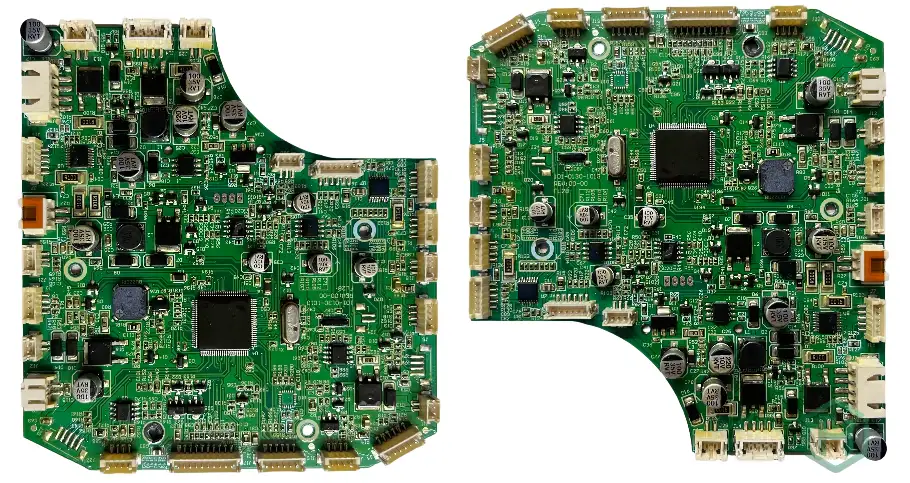
A physical therapy PCB is the control, sensing, power, and safety platform inside equipment such as nerve and muscle stimulators, therapeutic ultrasound units, rehabilitation controllers, and temperature-based therapy devices. Its design must deliver the intended energy while detecting credible faults, entering a defined safe state, and producing evidence that connects device risks to verified controls.
Key Takeaways
- Begin with the device's intended use, applied-part classification, essential performance, use environment, and risk analysis; no generic “medical-grade PCB” specification can replace those inputs.
- IEC 60601-1 spacing and insulation decisions depend on working voltage, means of protection, pollution degree, material group, altitude, and insulation construction. Do not copy one creepage value from another product.
- Nerve and muscle stimulators and ultrasonic physiotherapy equipment have different particular standards and energy paths. Their output monitoring and single-fault controls should not be treated as interchangeable.
- Separate commanded therapy output from independent limiting and shutdown. A firmware watchdog alone cannot control every hazardous-output failure.
- ISO 13485 is a quality-management-system standard; ISO 14971 defines medical-device risk management. Neither automatically certifies a bare PCB or complete product.
- Freeze production materials and processes early, then control every substitute and revision through risk, verification, and regulatory-impact review.
- The RFQ should identify safety-critical characteristics, traceability depth, test evidence, provisioning, and change-notification rules—not only BOM and Gerber files.
Contents
- What Makes a Physical Therapy PCB Different?
- Which Therapy Modality Drives the Design?
- How Should the Therapy Energy Safety Chain Work?
- How Do IEC 60601 Isolation and Leakage Requirements Affect the PCB?
- How Should Risk Controls Become Test Evidence?
- How Do EMC, Power, and Thermal Design Interact?
- What Do Software and Usability Standards Change?
- What Manufacturing Controls Matter for Medical PCBA?
- Do PCB Materials Need Biocompatibility Testing?
- What Should Be Included in Verification and Validation?
- What Should a Physical Therapy PCB RFQ Include?
What Makes a Physical Therapy PCB Different?
A therapy controller is not safer merely because it uses higher-reliability components. Safety comes from a documented architecture that identifies hazards, prevents or limits hazardous energy, detects failures, and verifies behavior in normal and single-fault conditions. The board also has to support the final device's electrical safety, electromagnetic compatibility, software lifecycle, usability, production, and post-market processes.
Before schematic capture, the device manufacturer should define:
- intended medical purpose, patient population, operator, therapy site, and contraindication-related system requirements
- professional, home, portable, wearable, or other use environment
- applied-part type and every patient/operator-accessible electrical path
- therapy waveform, frequency, voltage, current, power, duty cycle, exposure time, and acceptable error under normal and fault conditions
- essential performance and the safe state for loss of sensing, processor control, communication, power, or calibration data
- expected service life, cleaning/disinfection, storage, transport, ingress, drop, vibration, and temperature conditions
- applicable general, collateral, and particular standards plus target-market regulatory requirements
These are system-level decisions. A PCB supplier can review their implementation and manufacturability, but it cannot assign the device classification or essential performance on the customer's behalf.
Which Therapy Modality Drives the Design?
The energy-delivery method changes both the power architecture and the evidence required. IEC's current catalogue identifies IEC 60601-2-10 for the basic safety and essential performance of nerve and muscle stimulators and IEC 60601-2-5 for ultrasonic physiotherapy equipment. Other modalities may require different particular standards or only the general/collateral standards, depending on the intended use.
| Therapy modality | Board-level energy path | Credible PCB-related hazards | Design questions to resolve |
|---|---|---|---|
| TENS/NMES and other stimulation | Isolated or controlled pulse generator to electrodes | Excess amplitude or charge, DC component, wrong channel, stuck output, open/shorted electrode | What independently limits output? How are electrode faults and channel identity detected? |
| Therapeutic ultrasound | DC supply, switching power stage, matching network, transducer feedback | Excess acoustic output caused by drive/control error, overheating, poor coupling, wrong transducer | Which electrical measurements correlate with output, and what does the board do when feedback is invalid? |
| Heat/cold therapy | Heater, thermoelectric device, pump/fan, multiple temperature sensors | Burn, cold injury, runaway control, misplaced or failed sensor | Are sensing and cutoff independent? How are sensor open/short and poor thermal contact detected? |
| Rehabilitation motion control | Motor drive, encoders, force/position sensing, brakes/interlocks | Unintended motion, excessive force, lost position, uncontrolled restart | What removes torque, verifies motion, and prevents automatic restart after a fault? |
| Light-based therapy | LED/laser drive, optical feedback, temperature sensing | Excess optical exposure, wrong wavelength/source configuration, overheating | Which optical and thermal limits are independent of the main controller? Which particular standard applies? |
Do not infer safety from the therapy label alone. Two products sold as “physical therapy equipment” may differ in patient connection, delivered energy, operator access, environment, and regulatory classification.
How Should the Therapy Energy Safety Chain Work?
The therapy output should be reviewed as an end-to-end safety chain rather than a collection of isolated components:
- Command: the processor requests a validated therapy profile and channel.
- Generate: the power stage converts the command into electrical, acoustic, thermal, mechanical, or optical energy.
- Measure: independent sensing measures the variables needed to determine whether output remains within the defined envelope.
- Limit: hardware or sufficiently independent control constrains maximum energy, duty cycle, temperature, motion, or exposure time.
- Disconnect: a separate device can remove or inhibit output when the control path fails.
- Confirm and record: the system verifies the safe state, alerts the operator, and retains fault information required by the risk and service processes.
| Safety-chain element | Common hidden dependency | Review question | Fault-injection evidence |
|---|---|---|---|
| Therapy command | Corrupt configuration or wrong accessory ID | Can an invalid profile reach the power stage? | Modify configuration/accessory state and verify rejection |
| Output generation | Shorted switch, gate-driver fault, saturated transformer/inductor | Can one failed component create uncontrolled output? | Simulate/open/short defined components and measure response |
| Output sensing | Shared reference, common ADC, disconnected sensor | Is the monitor independent enough for the claimed control? | Force sensor open, short, drift, saturation, and stale data |
| Limit/cutoff | Same MCU, rail, clock, or firmware as main control | Does one shared failure defeat command and protection? | Halt the MCU or clock and verify energy removal |
| Patient/accessory path | Misconnection, damaged cable, wet connector, wrong electrode/transducer | Are connection and fault states distinguishable? | Test permitted and foreseeable connector/cable faults |
| Safe-state confirmation | Output command is off but energy remains | Is actual output measured after shutdown? | Create a stuck-output condition and confirm detection |
This matrix is not a substitute for the ISO 14971 risk file. It is a design-review tool for exposing controls that look independent on a block diagram but share power, firmware, sensing, or routing on the PCB.
How Do IEC 60601 Isolation and Leakage Requirements Affect the PCB?
IEC 60601-1 covers basic safety and essential performance for medical electrical equipment. The device manufacturer must identify means of operator protection (MOOP), means of patient protection (MOPP), applied parts, accessible parts, working voltages, insulation types, and fault conditions. These decisions flow into PCB spacing, slots, barriers, component selection, coating, transformer construction, connectors, and production tests.
Do not start with a copied creepage table value
Creepage is measured along a surface; clearance is measured through air. Required distances depend on factors such as working voltage, required means of protection, pollution degree, material group, altitude, overvoltage environment, and whether insulation is basic, supplementary, reinforced, or otherwise constructed and evaluated. Solder mask is not automatically accepted as a dependable insulation system. A slot may increase creepage, but its geometry, contamination exposure, mechanical strength, and manufacturing tolerance still matter.
Create an insulation coordination drawing that identifies:
- primary-to-secondary, secondary-to-patient, secondary-to-accessible, and signal isolation boundaries
- nominal and worst-case working voltages, transients, spacing, slots, and keepouts
- safety-critical components and their certification/rating evidence
- copper, via, pad, mounting hardware, shield, connector, heat sink, test point, and enclosure paths that cross or approach each boundary
- manufacturing tolerances, contamination controls, coating assumptions, and verification method
Leakage is a complete path, not one component value
Patient, touch, and earth leakage depend on the final power architecture, parasitic capacitance, filters, shields, cables, accessories, applied parts, and normal/single-fault configuration. Y-capacitors, isolated DC/DC converters, Ethernet/USB connections, programming fixtures, and grounded heat sinks can all alter the path. Pre-compliance measurements should use the representative enclosure, power supply, cables, accessories, and operating modes.
How Should Risk Controls Become Test Evidence?
ISO 14971:2019 defines a lifecycle process for medical-device risk management. The useful PCB deliverable is not a generic “risk considered” statement; it is a traceable chain from hazard to design requirement, implementation, production control, verification result, and change trigger.
| Hazardous situation | PCB design control | Manufacturing control | Verification evidence | Re-review trigger |
|---|---|---|---|---|
| Excess stimulation output | Independent amplitude/charge limit and output disconnect | Safety-component identity, polarity, value, programming state | Normal and single-fault waveform/energy tests | Component alternate, firmware, transformer, electrode accessory |
| Excess transducer/heater temperature | Independent sensor and cutoff; hotspot-aware layout | Sensor placement inspection, thermal-interface control | Worst-case thermal and sensor-fault tests | Enclosure, TIM, copper, airflow, duty cycle, supplier |
| Isolation breakdown | Defined MOP boundary, spacing, slots, rated components | Cleanliness, coating/assembly control, hi-pot where specified | Insulation review and electrical safety test | Material, layout, coating, connector, transformer, process |
| Therapy stops without warning | Power/clock supervision, watchdog, alarm path | Firmware/configuration verification and functional test | Loss-of-power/clock/sensor tests and alarm confirmation | MCU, oscillator, power tree, alarm component, software |
| Wrong channel/accessory | Keyed interface, ID or plausibility check, protected routing | Connector and harness verification | Misconnection and foreseeable misuse tests | Connector, cable, accessory, labeling, UI workflow |
| EMC causes unsafe output | Filtering, partitioning, return-path and shielding strategy | Placement, grounding, shield and cable controls | IEC 60601-1-2 immunity while monitoring essential performance | PCB stackup, cable, enclosure, firmware, power supply |
Risk control verification is not the same as overall device validation. Verification asks whether the implemented design meets its input requirements; validation asks whether the final device meets user needs and intended use under representative conditions.
How Do EMC, Power, and Thermal Design Interact?
IEC 60601-1-2:2014 with Amendment 1:2020 is the current consolidated edition in the IEC catalogue for electromagnetic disturbances. The PCB must support both emissions control and immunity while the device maintains its defined essential performance. A unit that resets safely may pass one risk decision; a unit that silently changes therapy output may not.
Partition high-energy switching, patient-connected analog sensing, digital control, radios, displays, and motor/relay loads by current path and susceptibility. Preserve return paths, minimize high-di/dt loop area, place filtering at the interface it protects, and keep protection-current flow away from sensitive references. Shielding and ferrites should implement a measured strategy, not compensate for an undefined ground system.
The power tree should define startup, shutdown, brownout, battery depletion, charger faults, reverse polarity, and partial-rail states. Confirm what the therapy output does before firmware is running and while rails decay. Supervisors, gate-discharge paths, pull resistors, and hardware interlocks often determine the real reset state.
Thermal analysis must include the final duty cycle, enclosure, ambient, airflow, patient contact, accessory loading, component tolerances, and fault conditions. Sensor placement should represent the controlled hazard, not only the coolest convenient PCB location. Copper spreading and thermal vias move heat but do not replace a validated path to the environment.
What Do Software and Usability Standards Change?
IEC 62304 defines medical-device software lifecycle processes, while IEC 62366-1 applies usability engineering to medical devices. These system standards still create concrete PCB requirements:
- enough protected nonvolatile memory for signed firmware, configuration, event logs, calibration, rollback, and recovery
- a watchdog and reset architecture whose independence matches the risk control claim
- controlled boot and update states that cannot unintentionally energize therapy outputs
- protected calibration and device-identity data with detectable corruption
- service and manufacturing interfaces that can be authenticated or locked before release
- controls, indicators, audible/visual alarms, and connector identification that support the validated user workflow
If the product is intended for the home healthcare environment, assess IEC 60601-1-11 and the actual home-use risks rather than assuming a clinic profile applies. Untrained users, transport, storage, supply quality, pets/children, cleaning, network availability, and accessory connection can change both hardware and usability controls.
What Manufacturing Controls Matter for Medical PCBA?
ISO 13485:2016 specifies quality-management-system requirements for organizations involved in medical devices and related services. In the United States, FDA's Quality Management System Regulation (QMSR) became effective on February 2, 2026 and primarily incorporates ISO 13485:2016 by reference, with additional FDA requirements. A supplier certificate is relevant evidence about its QMS scope; it does not approve the customer's device or replace supplier qualification.
Competitor medical-PCB pages commonly emphasize IPC class, tight tolerances, testing, and traceability. Those items matter, but a robust program also controls the transition from prototype to production. Prototype material, copper, finish, solder paste, coating, cleaning, programming, and test methods should either match the intended production process or have a documented bridge plan.
For each safety- or performance-critical characteristic, define the control and record:
- approved manufacturer part number and alternate policy for isolators, transformers, fuses, sensors, power devices, clocks, memory, and connectors
- laminate, copper, solder mask, surface finish, impedance, spacing, slot, cleanliness, and coating requirements
- AOI, X-ray, electrical test, boundary-scan, in-circuit, programming, calibration, and functional-test coverage as applicable
- lot/date-code, material batch, panel/board serialization, assembly batch, firmware/configuration version, test equipment, and test-result traceability
- nonconformance, rework/repair authority, deviation approval, retention, and change-notification requirements
IPC Class 2 or Class 3 should be selected by product requirements and risk, not by the word “medical.” Add customer-specific acceptance criteria where IPC workmanship alone cannot verify a safety control.
Do PCB Materials Need Biocompatibility Testing?
An internal PCB is not automatically a patient-contacting material. ISO 10993 biological evaluation is relevant when material contacts the patient directly or when the device's contact pathway, degradation, processing residue, or extractables/leachables analysis brings it into scope. The device manufacturer should define the nature and duration of contact and evaluate the finished contact system.
Conformal coating can support moisture, contamination, or spacing strategy, but “biocompatible coating” is not a universal solution. Coating chemistry, thickness, coverage, masking, adhesion, curing, repair, aging, cleaning agents, sterilization if applicable, and inspection all require control. RoHS/REACH declarations address restricted substances; they do not establish biological safety.
What Should Be Included in Verification and Validation?
Build the verification plan from design inputs and risk controls. Avoid promising fixed tests such as HALT, HASS, hi-pot, ionic cleanliness, or 100% X-ray unless the product and contract require them.
| Evidence layer | Representative activities | Ownership boundary |
|---|---|---|
| Bare PCB | Netlist, dimensional/visual inspection, stackup/material records, impedance coupon, microsection, cleanliness or coating-related evidence when specified | Fabricator to drawing and purchase order |
| PCBA | AOI/X-ray where applicable, polarity/value checks, programming, boundary scan/ICT, power-up, calibration and functional fixtures | Assembler to approved test specification |
| Engineering verification | Output limits, fault injection, insulation review, leakage, EMC pre-compliance, thermal, battery/power, software-hardware recovery | Device development team with qualified labs as needed |
| Design validation | Representative users, accessories, environment, cleaning, transport, intended workflows, misuse and clinical/use needs | Legal manufacturer/device owner |
| Production validation | Validated special processes, test method capability, process monitoring, lot release, traceability | Manufacturer and qualified suppliers per QMS agreements |
| Regulatory/conformity evidence | Complete-system safety, EMC, particular-standard, usability, software, biological and market-specific submissions | Legal manufacturer and conformity/regulatory partners |
Test both normal use and defined single faults while monitoring essential performance. A board may remain powered and responsive yet produce unsafe energy, an incorrect alarm, corrupted calibration, or a misleading display.
What Should a Physical Therapy PCB RFQ Include?
Device and safety context
- intended use, use environment, applied-part classification, essential performance, expected service life, and applicable standards/revisions
- therapy modality, output envelope, channel/accessory architecture, safe state, critical alarms, and risk-control characteristics allocated to the PCB
- insulation coordination drawing, working voltages, MOP boundaries, spacing/slot requirements, leakage-sensitive nodes, and test voltages/methods approved by the device team
Fabrication and assembly data
- Gerber/ODB++ or IPC-2581, drill, netlist, drawings, stackup, controlled impedance, materials, finish, solder mask, marking, panel, and IPC class/revision
- BOM with approved manufacturers and alternates, centroid, drawings, programming/calibration files, coating/cleaning, mechanical and thermal-interface instructions
- safety-critical component list, counterfeit/obsolescence controls, moisture sensitivity, storage, shelf-life, and handling requirements
Quality and evidence package
- prototype-to-production bridge, inspection/test coverage, sample size or 100% requirements, fixture ownership, golden units, limits, and raw-data/report format
- traceability fields, serialization, record retention, nonconformance/rework authority, deviation workflow, supplier-change notification, and PCN review window
- quantities, build stages, approved substitutions, packaging, delivery, and required certificates or reports
HILPCB can review the manufacturability, stackup, controlled-impedance, assembly, and agreed inspection/test package through turnkey PCB assembly. Materials, tolerances, QMS scope, traceability, special processes, functional testing, documentation, and lead time must be confirmed in the quotation.
Standards and Responsibility Scope
Common references may include IEC 60601-1:2005 with Amendments 1:2012 and 2:2020 for basic safety and essential performance; IEC 60601-1-2:2014 with Amendment 1:2020 for electromagnetic disturbances; IEC 60601-2-10:2012 with Amendments 1:2016 and 2:2023 for nerve and muscle stimulators; IEC 60601-2-5:2009 for ultrasonic physiotherapy equipment; IEC 60601-1-11:2015 with Amendment 1:2020 for home healthcare use where applicable; IEC 62304:2006 with Amendment 1:2015 for software lifecycle processes; IEC 62366-1:2015 with Amendment 1:2020 for usability engineering; ISO 14971:2019 for risk management; and ISO 13485:2016 for medical-device quality management systems. Confirm the applicable standards and nationally adopted editions with the device's regulatory and test partners.
The legal manufacturer owns intended use, classification, risk acceptability, essential performance, clinical/usability validation, regulatory strategy, supplier qualification, and final-device compliance. HILPCB is responsible only for the fabrication, assembly, inspection, documentation, and testing scope accepted in writing. PCB or PCBA delivery does not certify IEC 60601 compliance, market authorization, clinical effectiveness, biological safety, software safety, or complete-system EMC.
Common Questions
What is a physical therapy PCB?
It is the circuit board that controls, powers, senses, and monitors therapy equipment such as stimulators, therapeutic ultrasound units, rehabilitation controllers, and thermal therapy devices. Its safety requirements come from the complete device and intended use.
Does every physical therapy device need IEC 60601-2-10?
No. IEC 60601-2-10 applies to nerve and muscle stimulators. Ultrasonic physiotherapy equipment is covered by IEC 60601-2-5, while other modalities may have different particular standards or device-specific requirements.
What creepage and clearance should a medical PCB use?
There is no single medical-PCB value. Distances depend on working voltage, MOPP/MOOP allocation, pollution degree, material group, altitude, insulation type, and construction. Use the applicable IEC 60601 analysis for the final device.
Is ISO 13485 certification enough to make a PCB medical grade?
No. ISO 13485 concerns the supplier's quality-management system and its certified scope. The drawing, materials, processes, traceability, risk controls, test evidence, and final-device compliance still need to be specified and verified.
Does the internal PCB require ISO 10993 biocompatibility testing?
Not automatically. Biological evaluation depends on patient contact and the finished device's material/contact pathway. An enclosed internal PCB may be out of scope, while a coating, residue, or component in a patient-contact path may require evaluation.
Who is responsible for IEC 60601 compliance?
The legal manufacturer owns the complete-device compliance strategy and evidence. PCB fabricators and assemblers support that work by building to controlled requirements and supplying the agreed inspection, test, traceability, and change records.
Prepare the risk-linked fabrication and assembly package, then request a HILPCB review and quote for the PCB/PCBA scope and required evidence.