
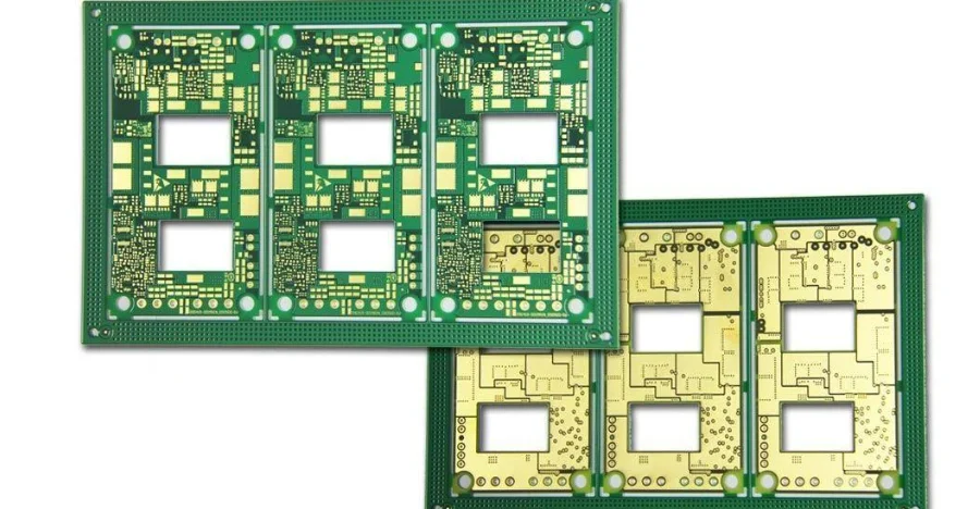
If you've ever tried to pull a clean ECG or SpO₂ trace out of a few millivolts of bioelectric signal, you know the whole problem eventually lands on one small board pressed against skin. Wearable patch PCB manufacturing isn't "just making circuits" — it sits at the intersection of biomedical engineering, materials science, RF, and precision fabrication. In a footprint the size of a coin, it has to deliver ultra-low-noise acquisition, extreme power efficiency, reliable flexible mechanics, and data handling that satisfies medical regulation.
Wearable patches are moving fast from consumer fitness trackers into clinical-grade devices — Holter monitors, continuous glucose monitors (CGM), and wireless vital-sign patches. That shift raises the bar on both design and manufacturing: comfort, data accuracy, and battery life have to coexist, and manufacturing consistency is what ultimately decides field reliability. This guide breaks down the five technical fronts where these designs are won or lost.
A wearable patch PCB must preserve low-level sensor signals, survive the released flex profile, control power and skin-side temperature, maintain its wireless link near the body, and support the final device's safety, biocompatibility, cybersecurity, and regulatory evidence. A board material or quality-system certificate alone does not prove those end-product outcomes.
Key Takeaways
- Partition low-level sensor inputs from clocks, switching regulators, radios, displays, and high-current return paths without creating uncontrolled reference discontinuities.
- Define static, service-flex, or dynamic bend zones and validate the actual stack-up, radius, cycle count, attachment, and enclosure.
- Tune and verify the antenna in its final enclosure and on-body use condition, not on a bare board in free space.
- Apply ISO 10993 evaluation to the final device's patient-contacting material system and contact conditions; do not assume a buried PCB is automatically a direct-contact material.
- Put flex, RF, EMC, programming, functional test, traceability, and change-control evidence in the RFQ.
Ultra-Low-Noise Analog Front-End (AFE) Layout
In a wearable patch, ECG amplitude is often only a few millivolts and PPG signals are highly sensitive to motion and ambient light. Any noise the board generates itself can bury the very signal you're trying to measure — which makes AFE layout the first and most important determinant of performance.
Noise comes mainly from thermal noise, supply ripple, digital crosstalk, and external EMI. Three layout disciplines do most of the work:
- Return-path-aware partitioning. Keep noisy switching and digital currents out of the sensor-input region while maintaining a continuous, intentional reference path. Split planes, 0 Ω links, or ferrites should be used only when the converter and component guidance supports them and the return-current boundary is understood.
- Symmetric differential routing. For differential inputs like ECG, match trace length, width, and spacing tightly and keep them clear of high-frequency digital lines. This maximizes CMRR. Apply the same differential-pair discipline to fast ADC clock lines to preserve signal integrity.
- Guard ring. Around high-impedance analog inputs, place a guard ring driven by the op-amp output. At near-identical potential to the input pin, it absorbs leakage from nearby traces before it reaches the input.
A clean reference ground underpins accurate ADC conversion: large ground pours give low-impedance return paths and absorb external EMI, and for the most sensitive AFE areas a metal shield can adds physical isolation. Powering the analog section from a dedicated LDO is a common, reliable route to low-noise performance.
Flex & Rigid-Flex Design: Bend Radius, Stackup & Reliability
A "no-feel" wearing experience means the patch has to conform to the body, which pushes the design toward FPC or rigid-flex. That improves comfort but introduces mechanical reliability challenges that don't exist on a rigid board.
Materials and biocompatibility. Polyimide is a common flex dielectric, but the final material system also includes coverlay, adhesive, stiffeners, surface finish, assembly residues, coating, enclosure, electrode, and skin adhesive. ISO 10993 evaluation is based on the final device's type and duration of body contact. A PCB buried behind a qualified barrier has a different exposure path from an electrode, adhesive, or enclosure surface that contacts skin.
Design rules that drive reliability:
- Bend radius control. In dynamic flex zones, bend radius is a primary lifetime driver. A common rule is dynamic bend radius ≥ 10× material thickness for single-layer flex. Mark bend zones clearly and keep components and vias out of them.
- Trace and pad design. Use arc transitions instead of 90° corners in bend zones to spread stress. In multilayer FPC, stagger traces between layers rather than stacking them, and use teardrop pads to strengthen the pad-to-trace junction against peel under vibration and flexing.
- Stackup and stiffeners. A typical flex PCB stack is coverlay, copper, adhesive, and PI. Assembly and connector regions usually need a PI or FR-4 stiffener for support, and stiffener design directly affects flatness and reliability. For patches that combine a rigid processing island with flexible sensor arms, rigid-flex PCB is ideal — at the cost of tighter manufacturing requirements.
These mechanical details decide production yield and long-term field reliability far more than most electrical choices.
A practical precision-flex (FPC) manufacturing flow
- Digital DFM review — evaluate bend radius and stiffener placement; run stackup stress checks to eliminate delamination risk up front.
- Biocompatible material selection — medical-grade adhesiveless FCCL, PI films, halogen-free flame-retardant materials; confirm ISO 10993 human-contact compliance.
- LDI fine-line imaging — laser direct imaging and vacuum etching to hold fine pitch and consistent impedance on ultra-thin substrates.
- Vacuum lamination and laser drilling — controlled-temperature vacuum lamination to avoid trapped bubbles, with UV-laser microvia registration.
- Surface finish and coverlay lamination — ENIG or ENEPIG for joint strength; precise coverlay alignment to prevent oxidation or cracking at bend points.
- Fatigue and reliability validation — 100% flying-probe test, then sample flexural-endurance testing to confirm long-term wear survival.
HILPCB engineer's note: the core challenge of flex circuits is dynamic reliability. For medical wearables we route along the neutral axis where possible and use teardrops to strengthen pads — maximizing both flexibility and durability.
Low-Power Design: PMIC, Battery & Thermal Management
For a patch that has to monitor continuously for days or weeks, power is the lifeline — and every microamp counts.
PMIC. Modern wearables lean on a highly integrated power management IC that buck/boosts from a small lithium cell to multiple stable rails, often bundling charging, fuel gauging, and power-path management. Choosing the right PMIC and following its reference layout carefully is the first step toward low power.
Power modes and clock-domain management. Hardware and firmware have to cooperate for fine-grained control:
- Multiple power modes — an active mode for acquisition, a connection-standby mode to hold the BLE link, and a deep-sleep mode with most blocks off.
- Power domains and clock gating — partition the system so unused blocks (e.g. NFC) can be fully powered down, and gate clocks to idle logic to cut dynamic power.
Thermal management. Even at low power, heat building up during long skin contact can cause discomfort and skew temperature or optical sensors. Use large copper pours as heat spreaders to move heat away from processors and RF chips, and place components to avoid concentrated hot spots against the skin.
Wireless Integration: BLE/NFC, Antenna Design & EMC
Data transmission is a core function — BLE for the main link, NFC for quick pairing — and fitting those RF functions onto a tiny flex board is genuinely hard.
Antenna design and body effects. PCB antennas (e.g. IFA) are space- and cost-efficient but very layout-sensitive:
- Keep-out zone. Enforce a strict clearance under and around the antenna — no traces, no copper — to protect radiation efficiency.
- Impedance matching. Match the antenna to the RF chip through a π or T network for a 50 Ω interface — critical for the RF section's performance.
- Body loading. The body acts as a dielectric: near skin, it absorbs RF energy and shifts antenna resonance, cutting signal strength. Simulate and measure with the patch on-body, then tune accordingly.
EMC and market access. Radio, EMC, electrical-safety, and medical-device obligations depend on the intended use and sales region. Design filtering, shielding, grounding, antenna tuning, operating modes, and test firmware early, then validate the finished device against the applicable requirements; bare-PCB testing does not grant product approval.
For a HILPCB quotation, specify the actual flex stack-up, minimum features, microvia structure, impedance targets, patient-contact boundary, material declarations, inspection, and reliability evidence. Capability and tolerance must be confirmed against the released construction; a fine-line, impedance, or "biocompatible material" label is not a substitute for build-specific evidence or final-device evaluation.
Medical Data Security & Regulatory Compliance
Wearables that handle protected health information (PHI) have to meet strict privacy rules such as HIPAA (US) and GDPR (EU). Security has to be system-wide, spanning hardware, firmware, and cloud.
On-device protection.
- Encrypted storage. Sensitive on-device data should be encrypted, ideally via an MCU with a hardware crypto engine (e.g. AES) rather than software alone.
- Secure boot. Verify a digitally signed, trusted firmware image on every boot to block malicious code.
Secure wireless. BLE provides encryption and authentication; designs should enforce the strongest pairing mode — LE Secure Connections — which uses ECDH key exchange to resist eavesdropping and man-in-the-middle attacks.
Quality management. For medical-device makers, ISO 13485 is the backbone, covering the full lifecycle from design through production and sale. For PCB manufacturing that means strict process control, traceability, and supplier management so every shipped board meets its defined specification — the institutional foundation for consistent quality.
What Should a Wearable Patch PCB RFQ Include?
- Schematics, BOM with approved alternates, fabrication and assembly data, flex stack-up, bend-zone drawing, stiffeners, mechanical files, panel constraints, and revision history
- Sensor and AFE bandwidth, noise and leakage limits, electrode or optical interface, grounding and shielding scheme, calibration method, and test fixtures
- Battery and charging architecture, current by operating mode, thermal and skin-contact limits, duty cycle, and power-measurement conditions
- BLE, NFC, or other radio bands, antenna geometry and keepout, enclosure and on-body tuning condition, matching network, and RF/EMC test modes
- Patient-contact materials and barriers, contact type and duration, cleaning or sterilization exposure, coating, cleanliness, traceability, and required material records
- Programming, secure provisioning, functional-test limits, flex-cycle and environmental tests, sample plans, retained data, quantities, packaging, and change control
Reference Standards and Responsibility Scope
Confirm current revisions and applicability with the device manufacturer and regulatory team.
- IPC-2223 — IPC
- IPC-6013 — IPC
- IPC-A-610 — IPC
- IPC J-STD-001 — IPC
- ISO 10993-1 — International Organization for Standardization
- ISO 13485 — International Organization for Standardization
- IEC 60601-1 — International Electrotechnical Commission, when applicable
- IEC 60601-1-2 — International Electrotechnical Commission, when applicable
HILPCB can fabricate and assemble the released flex or rigid-flex PCB and provide agreed inspection, traceability, and board-level test evidence. The medical-device manufacturer retains responsibility for intended use, risk management, patient-contact evaluation, clinical performance, software and cybersecurity, radio and EMC approval, sterilization or cleaning validation, and final regulatory submissions unless explicitly assigned in a validated agreement.
Frequently Asked Questions
Why is ultra-low-noise AFE layout so important on a wearable patch PCB?
Because ECG, PPG, and similar biosignals are inherently weak, even small board-generated noise can corrupt measurement accuracy. Careful grounding, shielding, differential routing, and clean analog power are what preserve signal quality.
What design rules matter most for flex and rigid-flex reliability?
Control bend radius, keep components and vias out of dynamic bend zones, use stress-friendly trace transitions, and add the right stiffener structure. These details directly set fatigue life and long-term field reliability.
How should power and thermal design be handled for long-wear patches?
Use a low-power PMIC architecture with multiple sleep modes and careful clock and power-domain control, plus heat spreading that avoids local hot spots against the skin. Long runtime is only useful if comfort and sensor accuracy hold up.
What must be validated before wearable patch mass production?
Validate the final device's patient-contact material system, flex life, sensor accuracy, thermal comfort, battery behavior, RF and EMC performance, secure data handling, manufacturing process, and applicable regulatory evidence. ISO 13485 supports the quality system but does not certify the patch's safety or clinical performance.
Conclusion
Wearable patch PCB manufacturing rewards teams that think past traditional board design. Electrical performance matters, but so do mechanical reliability, biocompatibility, power, RF, and data security — and every link is connected. A quiet AFE means nothing if the flex cracks; a flawless flex means nothing if the device fails certification.
A successful project needs a thoughtful design and an experienced manufacturing partner who understands medical constraints — one who supports you from DFM and material selection through prototype and small-batch assembly. Working with a specialist like HILPCB helps you avoid manufacturing traps, shorten time-to-market, and ship a reliable, safe, efficient product. Share your patch requirements and our engineers will review the flex stackup, materials, and compliance path before the first build.