
Flexible PCB Manufacturer | Fast-Turn FPC Prototyping to Volume Production
Turnkey flexible PCB manufacturer and flex circuit manufacturer providing quick turn flex pcb prototypes and cost-optimized mass production. From single-sided flex jumpers to complex multi-layer impedance-controlled flex circuits, HilPCB offers automated roll-to-roll processing, laser cutting, and precision SMT assembly.
Capabilities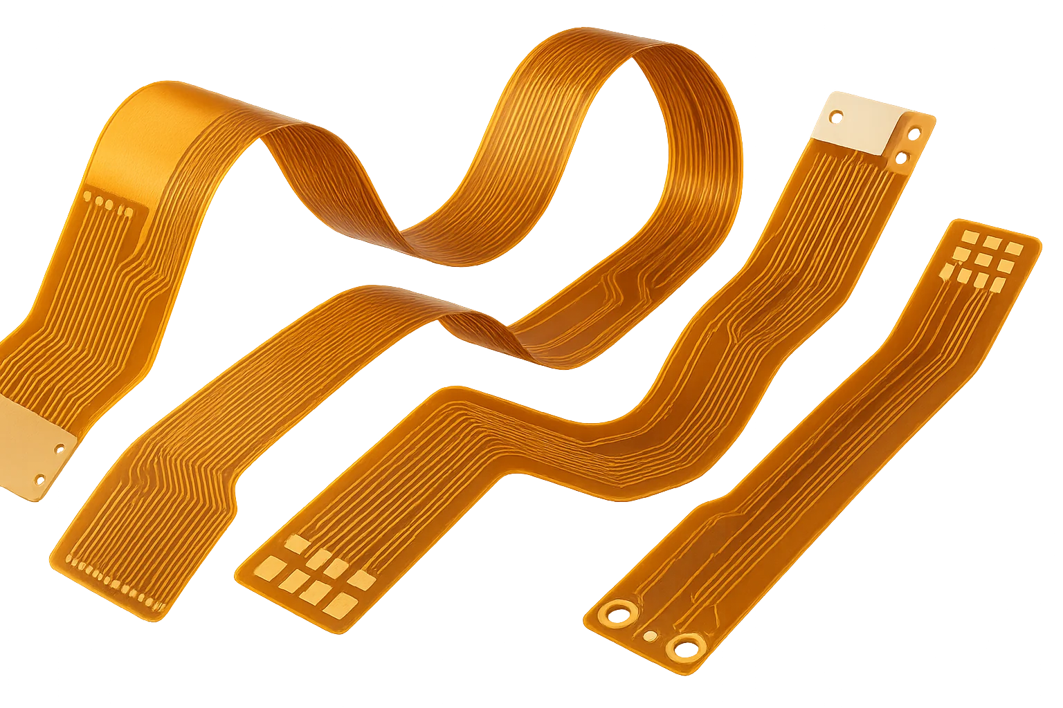
Why Choose Our Flex PCBs
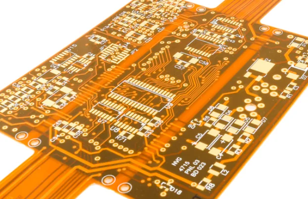
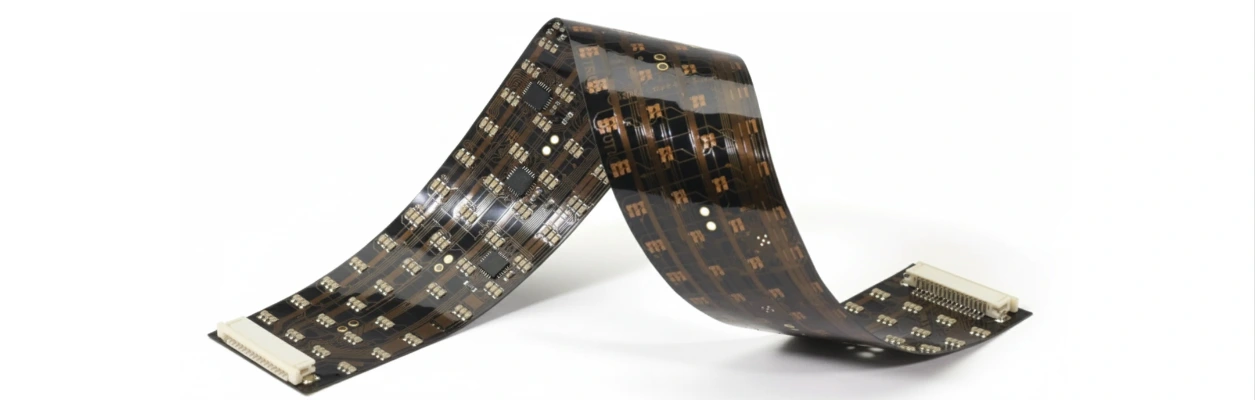
Thin, reliable interconnects for dynamic bending and tight spacesFlexible circuits reduce weight, enable tight routing and survive repeated motion. We support polyimide (PI) and LCP stacks for high-frequency or low-moisture applications. For assembly design tips that maintain bend reliability and yield, see our flex assembly guide. If your design includes rigid zones, consider rigid-flex PCBs to integrate stiff areas without connectors.
Critical Risk: Over-constraining the bend area (sharp corners, vias in flex region) can drive copper fatigue and early failure.
Our Solution: Use RA copper in dynamic zones, staggered traces, teardrops and coverlay fillets; keep the neutral axis at the conductor plane; and honor minimum bend radius R ≥ 10× t for dynamic designs unless simulation demonstrates otherwise.
- PI and LCP stackups for signal integrity and low moisture uptake
- RA copper for dynamic bends; ED copper for cost/performance balance
- Staggered routing, teardrops and filleted coverlay apertures
- Connector elimination via direct-flex interconnects
🚀 Quick Quote Request
📋 Get Full Capabilities
Manufacturing & Assembly for Flex
Process controls for adhesion, registration and handlingLaser direct imaging (LDI) controls registration for fine features; coverlay lamination uses controlled pressure and temperature to prevent squeeze-out. Stiffeners (PI, FR-4 or steel) are added for connector or screw regions. For assembly flow—reflow, selective solder and final test—see our SMT Assembly service and practical notes in flex assembly guide.
Impedance is verified with TDR; RF losses are checked on LCP builds. Handling instructions specify panel support and peel strengths to avoid conductor creep. AOI and 100% electrical test validate continuity and isolation.
- LDI imaging for fine-line features and tight registration
- Controlled coverlay lamination; fillet and relief design
- PI/FR-4/steel stiffeners for mechanical support
- TDR verification; coupon-based impedance correlation
Flex PCB Technical Specifications
Use listed values for design screening and confirm combined flex limits after file review
| Decision Area | Standard Route | Advanced Review | Confirmation Basis |
|---|---|---|---|
Base Materials | Polyimide (PI), ED copper | LCP, RA copper for dynamic flex | IPC-4202/4203 |
Layer Count | 1–4 layers | Up to 8 layers | IPC-6013 |
Board Thickness | 0.05–0.20 mm | Up to 0.40 mm | Process capability |
Min Trace/Space | 75/75 µm | 50/50 µm | Imaging capability |
Min Hole Size | 0.20 mm | 0.10 mm | Drill capability |
Impedance Control | ±10% | ±5% with TDR correlation | Test methods |
Coverlay | PI coverlay with acrylic/epoxy adhesive | No-flow coverlay, adhesive-less PI | IPC-4203 |
Stiffeners | PI/FR-4 stiffeners for connectors | Steel/aluminum stiffeners, countersink/counterbore | Assembly drawings |
Bend Radius (Dynamic) | R ≥ 10× t | R ≥ 6× t with RA copper and optimized layup | Design guideline |
Dynamic Flex Cycles | >100k cycles | >1M cycles | Customer test plan |
Surface Finish | ENIG, OSP | ENEPIG, Immersion Silver, Soft/Hard Gold | IPC-4552 |
Certifications | ISO 9001, RoHS/REACH | IATF 16949, ISO 13485, IPC-6013 Class 3 | Industry standards |
Lead Time | 5–10 days | Expedite options available | Production schedule |
Ready to start your PCB project?
Whether you need simple prototypes or complex production runs, our advanced manufacturing capabilities ensure excellent quality and reliability. Get your quote within 30 minutes.
FPC PCB Construction, Coverlay Options and Flexible PCBs Terminology
The term FPC PCB (flexible printed circuit) describes the same family as flexible PCBs and flex circuits. Different industries use FPC, flexible printed circuit, flex circuit and simply flex interchangeably. What matters commercially is the construction stack, because that is what drives price and yield.
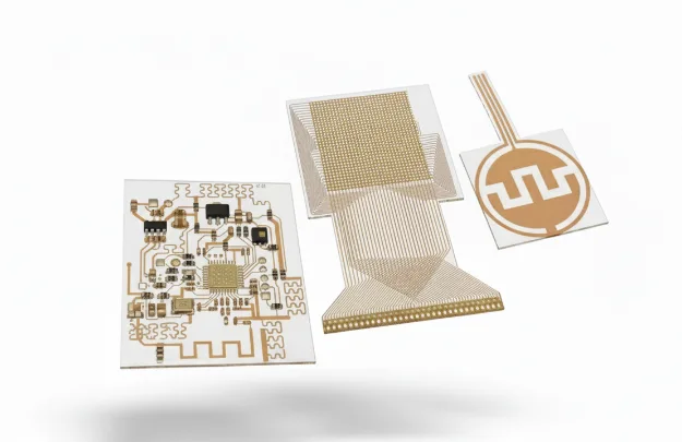
A single-sided FPC has one copper layer with a coverlay on the circuit side. It is the lowest-cost flex circuit and suits simple interconnects. Double-sided flex adds a second copper layer with plated through-holes; it roughly doubles routing capacity and is the most common flex construction in consumer and industrial assemblies. Multilayer flex builds additional layers with adhesiveless bonding for dense, high-density flex designs.
Coverlay versus photo-imageable solder mask. Polyimide coverlay gives the best mechanical and dielectric protection and is mandatory where a bend crosses the circuit. Photo-imageable flexible mask is cheaper and fine for rigidised or low-flex regions, but it is not a substitute in dynamic areas. Where a design bends repeatedly, coverlay edges must be offset from the bend line — a detail that is invisible on the Gerber yet decides whether the part survives.
Stiffeners and shielding. FR-4, polyimide or stainless stiffeners control connector mating and component support; silver or copper shielding layers control EMI. A high-reliability flex program usually specifies both, plus a defined bend axis on the fabrication drawing.
For a dense, fine-pitch FPC that also needs controlled impedance, review HDI alternatives or ask for an engineering review before layout freeze.
Polyimide Flex Circuit Fabrication: Material Grades, Thickness and Copper Systems
Almost every flexible PCB we build starts as a polyimide flex circuit. Polyimide (PI) is the default substrate for flexible printed circuits because it keeps mechanical strength across a very wide temperature range and survives the repeated bending that defines a flexible PCB application. Understanding which polyimide system you are buying is the difference between a flexible circuit that passes bend testing and one that cracks at the coverlay edge.
Substrate thickness. Standard polyimide flex cores run 12.5 µm, 25 µm and 50 µm. Thinner cores bend tighter but are harder to handle and more sensitive to copper grain direction; thicker cores support stiffer assemblies and connector retention. The bend radius you can achieve is driven mainly by the total stack thickness, not the core alone.
Copper type. Rolled annealed (RA) copper is the correct choice for dynamic-flex polyimide designs because its grain structure resists fatigue cracking; electrodeposited (ED) copper is acceptable for static bend or stiffened regions but performs poorly under repeated flexing. This single material decision determines whether a flex program survives life-cycle testing.
Adhesive versus adhesiveless. Adhesiveless laminates use a sputtered copper seed layer and give thinner stacks, better dimensional stability and higher temperature capability. Adhesive-based laminates cost less but thicken the stack and can outgas. For polyimide builds targeting fine-pitch or high-reliability duty, specify adhesiveless and state the copper type explicitly rather than leaving it to the fabricator.
When a polyimide flex circuit carries RF or high-speed nets, dielectric behaviour matters as much as mechanics; compare Rogers materials where controlled Dk/Df is required. For boards that must combine flexing with a rigid carrier, see rigid-flex PCB.
Design Guidelines for Reliable Flex
Keep copper out of tight bend areas; avoid vias in flex regions; use hatched planes where EMI allows. RA copper (rolled annealed) improves fatigue life versus ED. For materials trade-offs at RF, review high-frequency materials; for base film properties, see Kapton (polyimide) notes.
Need Expert Design Review?
Our engineering team provides free DFM analysis and optimization recommendations
Quality & Reliability Controls
Workmanship and inspection follow the quoted IPC-6013 class and quality plan. Electrical test, AOI, microsection, peel, fold or cyclic bend testing are selected against the design risk and stated acceptance method. For criteria and audit planning, see our IPC Class 3 overview. When rigid zones are required, compare a rigid-flex construction with a flex plus separate stiffener.
Flexible PCB Engineering Examples for Bend and Assembly Review
These common engineering scenarios show how HilPCB can review the flex stackup, bend zone, copper, stiffeners, assembly handling and test method together. The released drawing and quotation define the applicable construction and acceptance evidence.
Wearable sensor and medical patch circuits. Thin construction, repeated body movement, component islands and moisture exposure require the installed bend radius, neutral-axis location, RA copper, coverlay relief and strain path to be defined. Use the wearable patch manufacturing example to prepare bend and handling inputs.
Moving industrial interconnects. Repeated travel in a hinge, carriage or robotic mechanism needs a controlled flex length, bend direction, cycle profile and electrical monitoring threshold. The dynamic flex PCB example organizes the geometry, material and cycle-test questions.
Compact display and camera modules. Static installation bends may combine fine geometry, connectors, stiffeners and controlled impedance without needing a dynamic-flex construction. See the flexible display PCB example when defining layer orientation, assembly support and interface checks.
Engineering Assurance & Certifications
Flex PCB programs are reviewed for bend reliability, impedance and quotation-defined traceability.
Experience: strain or bend analysis can be included when the installed geometry and cycle profile justify it; the required model, test method and acceptance limit must be stated before release.
Expertise: engineering reviews copper grain direction, adhesive and coverlay construction, lamination controls, stiffeners and dimensional targets against the released drawing.
Authoritativeness: IPC-6013 class, ISO 9001 or IATF 16949 program scope and the required SPC or cycle-test records are confirmed in the quotation. For process-control questions, see our IPC Class 3 guidance and flex assembly guide.
Trustworthiness: state the required material lots, lamination references, coupon data and traveler records in the RFQ so the included traceability is agreed before order release.
For deeper design assurance across mixed constructions, explore rigid-flex PCB capabilities.
Flexible PCB RFQ Requirements
Send the latest Gerber or ODB++ package, NC drill data, fabrication drawing and stackup. Mark static and dynamic bend zones, installed bend radius, bend direction, flex length, layer orientation, stiffener material and thickness, connector interfaces, quantities and delivery target.
State PI or LCP preference, RA or ED copper, coverlay and adhesive requirements, impedance targets, surface finish, IPC-6013 class and the cycle count, mandrel, rate and acceptance criteria. Up to 8 layers, 50/50 µm geometry, >1M cycles and tight impedance are not automatically combinable; the released construction defines the applicable limits.
Flexible PCB Testing and Deliverables
Continuity and isolation testing address the electrical netlist; microsection and dimensional records address interconnect and registration; peel, fold or dynamic bend tests address the stated motion profile; and coupon TDR addresses controlled impedance when specified.
Define test method, sample count, bend radius, cycle rate, electrical monitoring, failure threshold and report format in the RFQ. HilPCB confirms which evidence is included, optional or customer-supplied before quotation.
Frequently Asked Questions
What minimum bend radius should I use for dynamic flex?
Should I choose PI or LCP for RF applications?
How do you control impedance on flex?
How do you prevent cracking near connectors?
What is a polyimide flex circuit made of?
Is FPC the same as a flexible PCB?
Experience Advanced PCB Manufacturing Excellence
From simple prototypes to complex production runs, our world-class factory delivers superior quality, fast turnaround and competitive pricing. Join thousands of satisfied customers who trust us with their PCB manufacturing needs.