
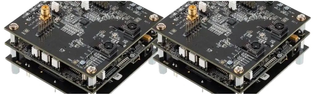
An alarm management PCB is the hardware platform that acquires security events, time-correlates them with video or access-control evidence, runs decision logic, records the result, and presents a reliable alarm to an operator or upstream system. It may be an NVR mainboard, a VMS server board, an edge analytics controller, or an industrial I/O gateway; the design must preserve the event-to-evidence chain even when a camera, network, disk, clock, or power rail fails.
Key Takeaways
- Start with the alarm workflow and failure response, not processor specifications. A fast board that loses event context or pre-event video is not a reliable alarm platform.
- Separate field I/O, network ingress, compute, storage, and management into fault domains so one failed interface cannot disable every evidence path.
- Budget network, memory, codec, accelerator, and storage bandwidth from simultaneous worst-case streams and events—not an average camera bitrate alone.
- Treat time as evidence: event inputs, video frames, access transactions, logs, and operator actions need a defined clock source, synchronization method, and holdover behavior.
- Use secure boot, protected keys, signed updates, rollback control, and recoverable firmware as a system architecture. Adding a TPM without an enrollment and recovery plan is incomplete.
- Contract the PCB/PCBA scope separately from ONVIF interoperability, video analytics accuracy, cybersecurity certification, and complete-system compliance.
Contents
- What Does an Alarm Management PCB Do?
- How Should the Hardware Be Partitioned?
- What Is the Event-to-Evidence Chain?
- How Should Alarm Inputs and Outputs Be Designed?
- How Do Video, Metadata, and Network Traffic Affect the PCB?
- How Do You Budget Compute, Memory, Power, and Thermal Margin?
- How Much Recording Storage Is Required?
- What Cybersecurity Functions Need Hardware Support?
- Which Faults Must the Platform Contain?
- What Should Be Verified Before Release?
- What Should the PCB and PCBA RFQ Include?
What Does an Alarm Management PCB Do?
The term describes a role rather than one fixed circuit. A compact recorder may combine camera Ethernet, video decoding, analytics, storage, digital I/O, and a display; a larger platform may process only metadata and events. Start by defining what must continue after each credible failure.
A complete alarm path normally includes six functions:
- Acquire: receive a dry contact, supervised loop, access-control event, camera analytic, tamper event, or system-health alarm.
- Normalize: debounce the input, validate its state, assign a source identity, and convert vendor-specific data into a common event model.
- Time-correlate: associate the event with synchronized video, access records, audio, sensor values, and system logs.
- Decide: apply priority, schedule, zone, dependency, suppression, and escalation rules.
- Preserve evidence: protect pre-event and post-event recordings, metadata, operator notes, and audit logs from overwrite or partial writes.
- Act and acknowledge: notify an operator or another system, control an output when authorized, record acknowledgement, and escalate if no response occurs.
The PCB transports and processes alarms, but it does not determine analytics accuracy, alarm procedure quality, or legal and operational compliance.
How Should the Hardware Be Partitioned?
Partition exposed interfaces from clocks, memory, and security-critical logic. The exact implementation varies, but these domains are typical.
| Hardware domain | Main functions | PCB priorities | Failure question |
|---|---|---|---|
| Field I/O | Contacts, supervised loops, tamper, relay/open-drain outputs, RS-485 | Surge/ESD protection, isolation strategy, filtering, creepage, connector protection | Can one field fault reset or damage the compute domain? |
| Network ingress | Camera, access-control, management, upstream VMS | Magnetics, common-mode control, return paths, ESD, controlled impedance | Is traffic still observable if one port or switch path fails? |
| Compute and memory | Rules, codecs, metadata, analytics, UI | DDR topology, PCIe routing, clock quality, PDN impedance, thermal escape | Does throttling or memory contention delay alarm handling? |
| Storage | OS, database, video, event clips, audit log | SATA/PCIe SI, power sequencing, hot-plug policy, power-loss handling | What evidence survives a disk or power failure? |
| Trust and management | Secure boot, keys, watchdog, service console, updates | Protected buses, write protection, recovery path, debug lockdown | Can the platform recover without exposing production secrets? |
| Power and time | DC input, converters, RTC, synchronization, holdover | Transient immunity, sequencing, brownout behavior, backup source | Are timestamps and committed records valid after an interruption? |
Dense SoCs, DDR, multiple Ethernet PHYs, PCIe/NVMe, and storage connectors often justify an HDI PCB, but HDI is not automatically required. Use it when BGA escape, via structure, routing density, or board area demands it. A conventional multilayer PCB may be more robust and economical when through-vias and ordinary pitch components provide enough routing freedom.
What Is the Event-to-Evidence Chain?
Production VMS platforms connect triggers, actions, schedules, recordings, procedures, acknowledgement, and incident reports. Hardware requirements should mirror that chain. This matrix connects each software promise to a measurable PCB dependency.
| Chain stage | Evidence that must exist | Hardware dependency | Release test |
|---|---|---|---|
| Event arrives | Source ID, electrical/logical state, first timestamp | Protected I/O, PHY, interrupt path, monotonic counter | Inject simultaneous events and verify none are lost or merged |
| Rule evaluates | Rule version, schedule, dependencies, decision time | CPU/NPU load margin, deterministic queueing, valid RTC | Run peak video load while measuring event-to-decision latency |
| Context is attached | Pre-event video, metadata, access transaction, health state | Ring buffer, memory bandwidth, synchronized clocks | Trigger before and during network jitter and inspect alignment |
| Evidence commits | Clip, database row, hash or integrity metadata, audit log | Storage queue, power-loss policy, filesystem/database behavior | Interrupt power during write and verify recovery and completeness |
| Alarm is presented | Priority, location, procedure, live/recorded view | Display/network path, GPU if used, client-server availability | Remove one display or network path and verify defined fallback |
| Operator acts | User identity, acknowledgement time, notes, action result | Authentication device, secure clock, durable audit storage | Attempt duplicate, delayed, and unauthorized acknowledgement |
| Alarm escalates/closes | Escalation target, closure reason, retained evidence | Communications redundancy, retention policy, log capacity | Disconnect the primary notification path and verify escalation |
Define latency endpoints. “Alarm latency” may mean input-to-interrupt, camera-to-server, decision-to-display, or display-to-notification; specify and test each required interval.
How Should Alarm Inputs and Outputs Be Designed?
Field wiring is often the controller's most exposed electrical interface. Do not label a connector only “alarm in.” Define each channel type, normal and maximum voltage, transient environment, source/sink current, polarity, reference, cable length, and fault states.
Input design checkpoints
- Protection: coordinate current limiting, TVS selection, filtering, and grounding with the expected surge and ESD environment. A TVS footprint alone does not establish immunity.
- Isolation: decide whether channels need galvanic isolation, grouped isolation, or a shared reference. Isolation voltage, working voltage, creepage, clearance, and barrier lifetime are different requirements.
- State discrimination: supervised loops may need to distinguish normal, alarm, open-circuit tamper, and short-circuit tamper states. Resistor values and thresholds belong in the system specification.
- Debounce and filtering: contact bounce and EMI can create alarm floods. Define hardware filtering, sampling rate, software debounce, minimum active time, and retrigger behavior together.
- Diagnostics: consider per-channel open/short detection, test excitation, stuck-state detection, and readable protection-fault indicators where the application needs them.
For outputs, state load voltage/current, inductive behavior, reset default, isolation boundary, contact rating, and fail-safe or fail-secure behavior. Relays have finite switching life; semiconductor outputs require leakage, thermal, and failure analysis. The system owner determines what each output may control.
How Do Video, Metadata, and Network Traffic Affect the PCB?
ONVIF separates several functions that marketing copy often collapses into “compatible.” Profile T addresses advanced IP video streaming, including H.264/H.265, motion and tampering events, metadata streaming, and conditional features such as digital I/O and relay outputs. Profile M covers analytics metadata, object classification, event interfaces, rule configuration, and optional MQTT transport. Profile G covers edge recording and retrieval. A product is only conformant when the implemented device or client passes the applicable profile process; using an Ethernet PHY or ONVIF-capable software library does not make the PCB conformant.
For board design, translate the supported modes into simultaneous traffic cases:
- maximum active camera streams, resolutions, frame rates, codecs, and configured bitrate limits
- concurrent live view, recording, playback, export, metadata search, analytics, and firmware update traffic
- multicast versus unicast behavior and the number of client sessions
- pre-event and post-event buffering during bursts
- edge-recording retrieval after a network outage
- management traffic, access-control events, MQTT, audio, and redundancy heartbeats
Then budget every bottleneck: Ethernet MAC/PHY capacity, switch fabric, PCIe lanes, memory bandwidth, decoder/encoder sessions, storage writes, and northbound network links. Protocol line rate is not usable application throughput; framing, retransmission, encryption, filesystem work, and competing traffic consume margin.
Route high-speed interfaces to component and fabricator constraints for planes, impedance, matching, via stubs, launches, and return paths. Place Ethernet magnetics and ESD structures to PHY/connector guidance. Resolve DDR, PCIe, SATA, USB, and display topology and stackup before routing.
How Do You Budget Compute, Memory, Power, and Thermal Margin?
Alarm processing competes with video decode, AI inference, storage, encryption, UI rendering, and background maintenance. Average CPU utilization hides short bursts—the exact moment multiple analytics events may arrive. Build a workload matrix with ordinary, busy, degraded, and recovery states.
| State | Concurrent workload to include | Design risk |
|---|---|---|
| Ordinary | Recording, rule processing, health monitoring | Underestimating continuous memory and storage traffic |
| Event burst | Multiple analytics events, pre/post buffers, notifications, clip locks | Queue overflow or delayed alarm presentation |
| Investigator use | Multi-camera playback, timeline search, export, incident report | Read traffic starving live recording writes |
| Degraded network | Retries, reconnects, edge-storage retrieval, duplicate events | Traffic and database burst after reconnection |
| Update/recovery | Signed image verification, decompression, logging, rollback | Brownout or watchdog reset leaving an unbootable unit |
The PDN must support load steps without violating rail limits. Follow vendor sequencing, decoupling, sensing, and layout requirements; validate regulator stability with the selected capacitors. Brownout detection needs a defined response before rails collapse.
Thermal design starts with a power map. Model the SoC/accelerator, memory, PHYs, regulators, and storage at the heaviest simultaneous workload. Define ambient, airflow, enclosure, heat-sink interface, sensors, throttling, and shutdown. Copper and vias do not replace an enclosure-level heat path.
Timekeeping deserves equal attention. Use a stable RTC and define the behavior when NTP/PTP or another time source is unavailable. Logs should distinguish wall-clock time from a monotonic event sequence so a clock correction does not reorder evidence. If a battery or supercapacitor is used, document replacement, leakage, shipping, and end-of-life behavior.
How Much Recording Storage Is Required?
Storage must be sized from actual configured bitrates and retention policy. For continuous recording, an initial decimal-capacity estimate is:
Required video capacity (TB) = aggregate bitrate (Mbps) × 0.0108 × retention days
For example, sixteen streams averaging 4 Mbps produce an aggregate 64 Mbps. Thirty days of continuous video requires about 20.7 TB before filesystem overhead, reserved free space, metadata, audio, redundancy, export workspace, bitrate variation, and failed-drive rebuild margin. Event-only recording needs a different model based on trigger frequency, pre/post duration, and simultaneous events.
| Storage input | What to specify | Why it matters |
|---|---|---|
| Stream profile | Actual configured bitrate or measured range per mode | Resolution alone does not determine storage |
| Retention | Continuous/event policy and days by camera or event class | Critical clips may need longer retention than ordinary video |
| Redundancy | RAID or replication objective and rebuild assumptions | Usable capacity differs from raw disk capacity |
| Failure behavior | Recording destination after disk, array, or network loss | The system needs a defined degraded mode |
| Power loss | Hold-up, flush policy, protected cache, database recovery | An acknowledged alarm should not point to a corrupt clip |
| Serviceability | Drive monitoring, replacement, rebuild alarm, thermal limits | Storage is an operational subsystem, not only a connector count |
RAID can maintain availability after defined drive failures, but it is not a backup and does not prevent deletion, malware, controller failure, or site loss. Validate sustained write performance during playback, export, rebuild, and edge-recording synchronization—not just a sequential benchmark on an empty array.
What Cybersecurity Functions Need Hardware Support?
Security surveillance equipment is itself a networked target. Hardware should support a chain of trust from immutable or protected boot code through the operating system and application. NIST SP 800-193 frames firmware resilience around protecting against unauthorized changes, detecting changes that occur, and recovering securely; those three outcomes are more useful than a checklist of security chips.
A production architecture may include:
- verified or secure boot anchored in protected device keys
- signed firmware and configuration packages with anti-rollback policy
- protected key generation and storage using a TPM, secure element, or SoC security block when justified
- a recovery image or authenticated service path that survives an interrupted update
- hardware watchdogs and brownout handling with boot-loop detection
- locked or authenticated debug, test, and manufacturing interfaces
- unique device identity and a controlled provisioning record
- encrypted management and video paths where required by the system threat model
- auditable update, enrollment, key rotation, decommissioning, and ownership-transfer procedures
The PCB team must reserve the required interfaces, memory, write-protect controls, recovery straps, and manufacturing fixtures. The product owner must define the trust model, certificate authority, update service, vulnerability process, and field recovery. Encryption claims should state the protocol, endpoint, key custody, and operating mode; “AES supported” does not prove end-to-end protection.
Which Faults Must the Platform Contain?
The following fault-domain matrix is the second design asset. It forces the team to define degraded operation before qualification testing.
| Injected fault | Minimum observable response | Useful board provisions | Evidence to retain |
|---|---|---|---|
| Camera/network path lost | Health alarm; unaffected sources continue | Independent ports/switch paths, link diagnostics, edge retrieval support | Disconnect/reconnect time and missing interval |
| Storage full or failed | Recording fault without blocking event processing | Separate OS/evidence storage where justified, drive telemetry | Last successful write, affected channels, operator action |
| Time source lost/jumps | Time-quality alarm; monotonic order preserved | RTC, holdover source, monotonic counter | Old/new time, offset, synchronization state |
| Brownout/power removal | Controlled reset or recovery; no silent database corruption | Supervisor, power-good, hold-up where required, recovery image | Reset cause, incomplete transactions, recovery result |
| Processor overload | Load alarm, bounded queues, defined feature shedding | Watchdog, performance counters, thermal sensors | Dropped/deferred work and alarm latency |
| Overtemperature/fan fault | Throttle or shutdown by policy; critical alarms remain visible if possible | Sensors near hotspots, fan tach/control, independent supervisor | Temperature history and protection action |
| Field input short/surge | Fault confined to channel or I/O domain | Current limiting, isolation, coordinated protection | Channel fault and diagnostic state |
| Primary alarm output fails | Detect or declare loss; use planned alternate path | Feedback contact, redundant channel, monitored driver if required | Commanded versus observed output state |
Do not label every duplicated component “redundant.” Redundancy only exists if the alternate path avoids the same power source, connector, switch, software process, clock, and storage dependency that can disable the primary path.
What Should Be Verified Before Release?
Verification needs both PCB-level measurements and scenario-based system tests. Start with normal electrical bring-up, then test the event chain under maximum load and injected faults.
- Power and signal integrity: rail sequence, ripple, transient response, clock quality, DDR margin, high-speed channel compliance, Ethernet error counters, and storage-link stability.
- I/O robustness: thresholds, debounce, open/short diagnosis, polarity mistakes, ESD/surge plan, relay or output load behavior, and reset defaults.
- Evidence timing: event timestamp accuracy, frame/event correlation, prebuffer and postbuffer, clock loss, time correction, and multi-source ordering.
- Performance: concurrent recording, analytics, playback, export, encryption, alarm bursts, reconnect storms, and storage rebuild.
- Thermal: worst-case workload at the declared ambient and airflow limits, including blocked-filter or fan-fault conditions when applicable.
- Recovery: sudden power removal, interrupted update, corrupt configuration, full disk, failed drive, watchdog reset, and authenticated factory/service recovery.
- Manufacturing: AOI, X-ray where hidden joints justify it, boundary scan or functional test where designed, programming/provisioning records, connector tests, and serialized traceability.
Pre-compliance testing should use the product's real enclosure, cables, power supply, peripherals, and operating modes. A bare PCB result cannot establish complete-system EMC, environmental, cybersecurity, or alarm-system compliance.
What Should the PCB and PCBA RFQ Include?
Provide enough context for the manufacturer to review the real risk rather than quote only layer count and dimensions.
Design and fabrication data
- Gerber/ODB++ or IPC-2581 data, drill files, netlist, drawings, stackup, impedance table, controlled-depth features, and panel requirements
- board outline, thickness, copper weights, material or performance needs, surface finish, solder mask, marking, and applicable IPC class/revision
- DDR, PCIe, SATA, Ethernet, USB, display, and clock interfaces that need special routing or fabrication review
- approved geometry-adjustment authority and coupon/TDR reporting requirements
Assembly and provisioning data
- BOM with manufacturer part numbers and approved alternates, centroid, assembly drawings, polarity/orientation notes, and special handling
- BGA/LGA/connector requirements, thermal interfaces, press-fit or mechanical operations, conformal coating or cleaning requirements if applicable
- firmware images, programming sequence, unique identity/key provisioning boundary, debug-lock sequence, and acceptance records
Product and verification context
- field input/output electrical envelopes, isolation concept, cables, external protection assumptions, and load types
- power input range, sequencing, peak load, brownout behavior, backup/hold-up needs, and storage power policy
- stream/channel workload matrix, retention model, event latency endpoints, thermal environment, enclosure/airflow, and fault-injection acceptance criteria
- quantities, prototype and pilot stages, test coverage, sample retention, serialization, change control, deviation approval, and required reports
HILPCB can review the manufacturability, stackup, controlled-impedance, assembly, and agreed test package through turnkey PCB assembly. Actual materials, tolerances, inspection, functional test, security provisioning, evidence, and lead time must be confirmed in the quotation.
Standards and Responsibility Scope
Relevant references may include IEC 62676-1-1 and IEC 62676-4 for video surveillance system requirements and application guidance; ONVIF Profile T, Profile M, and Profile G for applicable IP video, metadata/event, and recording interfaces; IEC 60839-11-1 for electronic access-control systems; NIST SP 800-193 for platform firmware resilience; IPC-2221 for generic PCB design; IPC-6012 for rigid PCB qualification/performance; and IPC-A-610 for electronic assembly acceptability. Use the contractually specified revision and only claim conformity after the applicable product, implementation, and evidence have been assessed.
The system owner defines alarm priorities, response procedures, retention, privacy, analytics performance, cybersecurity objectives, redundancy, and regulatory scope. HILPCB is responsible only for the PCB fabrication, assembly, inspection, provisioning, and testing accepted in writing. PCB manufacture does not certify ONVIF conformance, video analytics accuracy, GDPR compliance, fire or intrusion-alarm approval, or complete-system safety and security.
Common Questions
Is an alarm management PCB the same as an NVR motherboard?
Not always. An NVR motherboard records and manages video, while an alarm management board may also be a VMS server, edge controller, access/security integration board, or I/O gateway. The defining function is preserving the event-to-evidence and response chain.
Does ONVIF support alarm events?
Yes, within specific profiles and supported features. Profile T includes motion and tampering events and metadata streaming; Profile M addresses analytics metadata and event interfaces; Profile G addresses edge recording and retrieval. Conformance belongs to the tested product implementation, not the bare PCB.
How do I calculate surveillance storage capacity?
For continuous video, multiply aggregate configured bitrate in Mbps by 0.0108 and by retention days to estimate decimal TB. Then add filesystem, metadata, audio, reserved-space, redundancy, rebuild, export, and bitrate-variation allowances.
Should alarm inputs be isolated?
Isolation depends on field voltage, grounding, cable environment, surge exposure, safety requirements, and acceptable common-mode coupling. Define the interface and fault environment first; then select channel, group, or system-level isolation with the required creepage and clearance.
What is the most important alarm PCB reliability test?
There is no single test. The strongest evidence comes from running the complete event chain under peak video/storage load while injecting network, clock, storage, thermal, I/O, firmware-update, and power faults, then verifying alarm delivery and evidence recovery.
Can RAID guarantee that alarm video will not be lost?
No. RAID can tolerate defined drive failures, but it does not replace backup, replication, cybersecurity controls, power-loss protection, retention policy, or database recovery testing.
Build the quotation package around the required alarm workflow and degraded modes, then request a HILPCB review and quote for the PCB, assembly, and agreed verification scope.