
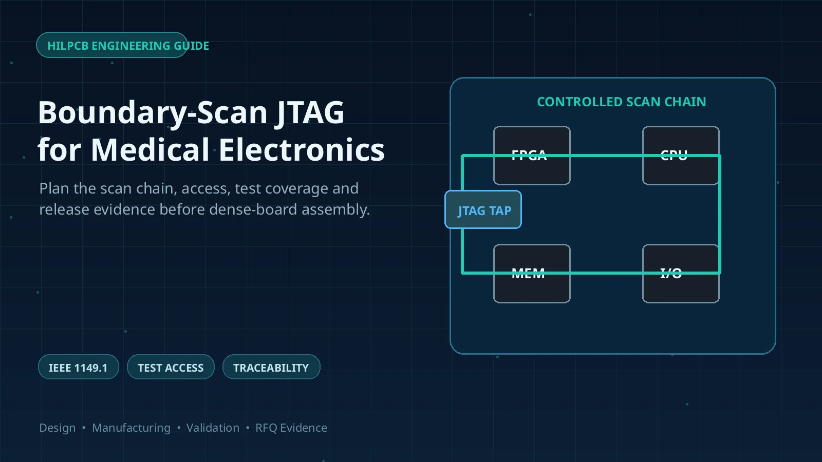
Boundary-scan is a structural test method defined by the IEEE 1149.1 test-access-port and boundary-scan architecture. It uses test cells at supported digital device pins to drive and observe board interconnects through a serial JTAG interface, making it valuable when BGAs, dense routing, rigid-flex construction, or limited test-pad area reduce physical probe access.
For medical imaging and wearable PCBs, Boundary-scan can improve manufacturing fault detection and diagnosis, but it does not prove analog accuracy, patient safety, biocompatibility, EMC, cybersecurity, software correctness, or clinical performance. Those claims require separate product-level risk controls and verification.
Key Takeaways
- JTAG is an access interface used for several purposes; Boundary-scan structural test, processor debug, and device programming are related but distinct capabilities.
- Test coverage depends on the exact devices, BSDL files, netlist, chain architecture, pin-cell capabilities, controllability, and observable endpoints—not on whether a board merely has a JTAG header.
- Boundary-scan can detect many opens, shorts, and stuck interconnect conditions on accessible digital nets, but it does not inspect solder-joint shape or measure low-noise analog performance.
- SPI, AOI, X-ray, flying probe, ICT, Boundary-scan, functional test, and system qualification answer different questions. A defensible test plan maps each failure mode to the method that can detect it.
- JTAG access is also a security boundary. Development, manufacturing, release, service, and recovery states should be designed before any irreversible lock operation.
- Medical-device compliance remains the legal manufacturer's responsibility. A PCBA supplier can provide manufacturing and test evidence but cannot certify the finished device by inference.
Contents
- What Can Boundary-Scan Prove?
- How Should Fault Coverage Be Defined?
- What JTAG DFT Rules Matter Before Layout Freeze?
- How Do Boundary-Scan and Other Tests Work Together?
- What Changes for Rigid-Flex and Low-Noise Medical Boards?
- How Should JTAG Security and Provisioning Be Controlled?
- How Do Coating and Selective Soldering Affect Test?
- What Evidence Should Production Retain?
- What Should Be Included in the RFQ?
What Can Boundary-Scan Prove?
In an IEEE 1149.1-capable device, boundary cells can capture or drive supported pin states while the Test Access Port (TAP) controller selects instructions and data registers. Devices are connected in a serial scan chain through TDI and TDO, with TCK and TMS controlling the operation. A valid BSDL file describes the device's instruction set, boundary register, pin mapping, cell behavior, and other implementation details needed by test-generation tools.
An interconnect test drives a pattern from one supported pin and captures it at another endpoint. It can diagnose modeled opens, shorts between distinguishable nets, or stuck logic states. Simple non-scan devices or connectors may also be testable when scan-capable devices provide valid drive and observation paths.
That capability has firm limits:
- A hidden BGA joint can be electrically testable without being visually or geometrically inspected.
- An analog net may be forced to a digital threshold without proving gain, offset, noise, bandwidth, common-mode behavior, or sensor accuracy.
- Power and ground integrity cannot be declared good merely because the JTAG chain responds.
- A successful scan does not prove firmware behavior, timing margin, radio performance, battery life, alarm performance, or regulatory compliance.
- Coverage varies by instruction support and boundary-cell type. A BSDL file's existence does not guarantee that every package pin or board net is controllable and observable.
Boundary-scan is therefore strongest as a structural-test layer with explicit exclusions, not as a replacement for all physical and functional verification.
How Should Fault Coverage Be Defined?
Coverage should be reported against a defined fault universe. A single percentage without denominator, exclusions, test stage, or software revision is not useful evidence.
| Product risk or defect | Boundary-scan contribution | Complementary evidence | Important exclusion |
|---|---|---|---|
| Open or short on a digital interconnect between supported scan pins | Often strong structural coverage | AOI/X-ray for physical context; functional test for behavior | Coverage depends on cell capability, topology, and distinguishable fault model |
| BGA or CSP hidden-joint defect | Can detect an electrical interconnect failure on covered nets | X-ray for solder geometry; cross-section for targeted process investigation | Boundary-scan does not show void shape, head-in-pillow, or joint morphology |
| Connector or flex-tail continuity | Possible when both ends are controllable/observable or a loopback is provided | Flying probe, fixture continuity, mating and flex test | Uninstrumented contacts and shields remain outside coverage |
| Resistor, capacitor, diode, or non-scan logic | Limited cluster test may be possible | Flying probe or ICT; functional stimulus | Value tolerance and analog behavior may not be measurable through digital cells |
| ECG/PPG/ultrasound analog-front-end performance | Usually no direct proof under IEEE 1149.1 | Calibrated functional test for noise, gain, offset, bandwidth, channel matching, and protection | A digital pin-state test cannot establish diagnostic signal quality |
| Power rail sequencing, ripple, and sleep current | May help command device states | Oscilloscope, DMM, current analyzer, programmable supply, firmware-controlled test | JTAG debug can control code; it is not itself a precision current measurement |
| Firmware authenticity and security configuration | May provide a controlled programming path | Signed-image verification, key provisioning records, readback/attestation, final access-state check | Programming success does not prove secure boot, confidentiality, or lifecycle security |
| EMC, electrical safety, usability, biological evaluation, or clinical performance | No direct compliance evidence | Product-level verification and validation under the applicable risk plan | PCBA structural test cannot certify the medical device |
The useful output is a net- and fault-level report: testable nets, partially testable nets, untestable nets, fault types covered, constraints, reasons for exclusions, and the other station responsible for each gap. This prevents “95% coverage” from hiding a small number of high-risk untested signals.
What JTAG DFT Rules Matter Before Layout Freeze?
Boundary-scan performance is largely decided during architecture and schematic design. A late request to “add JTAG test” cannot recover missing scan endpoints, inaccessible TAP connections, uncontrolled resets, or undocumented chain order.
Device and chain architecture
- Select exact component variants with verified, package-matched BSDL data.
- Document chain order, TDI/TDO direction, bypass behavior, ID codes, voltage domains, and expected device population.
- Decide whether one chain or partitioned chains provide better fault isolation, boot behavior, serviceability, and fixture access.
- Define behavior for optional or depopulated devices so one missing component does not make the chain ambiguous.
- Control resets, enables, boot straps, transceivers, isolation devices, and clocks needed to place the board in a safe test state.
TAP electrical and physical access
- Route TCK, TMS, TDI, TDO, optional reset, reference voltage, and ground with known logic levels and device-vendor requirements.
- Evaluate TCK loading, stubs, fanout, connectors, buffers, and cable/fixture effects on larger chains.
- Provide accessible production pads or a keyed connector, with sufficient ground reference and mechanical protection.
- Keep TAP access available through the intended manufacturing stage; do not coat, bury, or permanently lock it before required tests and provisioning complete.
- Define test power sequencing and safe limits for attached sensors, batteries, displays, emitters, motors, and patient-connected circuitry.
Release the netlist, BOM, schematics, BSDL files, chain description, constraints, and test requirements under revision control. Identify ownership of vectors, models, adapters, source scripts, licenses, and diagnostics. Run testability analysis before layout release and after substitutions or netlist changes.
For a rigid-flex PCB, also treat the rigid-to-flex transition, stiffener edges, connector tail, bend region, and assembly fixture as explicit nets and mechanical risks rather than assuming the scan chain “sees” the entire structure.
How Do Boundary-Scan and Other Tests Work Together?
A medical or wearable PCBA usually needs three evidence layers: process inspection, structural electrical test, and product-specific functional test.
| Method | Best question answered | Typical limitation |
|---|---|---|
| SPI | Was solder paste deposited within the validated print-process limits? | Does not prove placement, reflowed joint integrity, or electrical behavior |
| AOI | Are visible parts, polarity, alignment, markings, and joints consistent with the program? | Limited by line of sight, program quality, and defect library |
| X-ray | Do hidden structures show density or geometry patterns associated with defined defects? | Interpretation, overlap, resolution, and angle limit certainty; not a functional test |
| Flying probe or ICT | Are accessible nets and components electrically consistent with the test model? | Physical access, fixture/program cost, speed, and analog topology constrain coverage |
| Boundary-scan | Do modeled digital interconnects respond correctly through supported scan cells? | Cannot cover every net, analog parameter, or physical defect morphology |
| Functional test | Does the assembly perform specified functions under defined stimuli and limits? | Fault isolation may be weak; unexercised states can remain untested |
| System qualification | Does the finished product meet safety, EMC, environmental, software, security, usability, and performance requirements? | Product-specific, controlled by the legal manufacturer and applicable market pathway |
Sequence tests to shorten diagnosis. Inspection and structural tests should catch process defects before a functional station reduces an open interconnect to a vague “device will not boot” failure. Functional tests then exercise specified product behavior.
For prototypes and small lots, small-batch assembly may pair Boundary-scan with flying probe to avoid a full bed-of-nails fixture. At higher volume, integration with ICT or a functional station can reduce handling, but only if test ownership, software versions, electrical isolation, and result traceability are controlled.
What Changes for Rigid-Flex and Low-Noise Medical Boards?
Rigid-flex wearables concentrate several test constraints: minimal pad area, fine-pitch packages, flex-tail connectors, repeated handling risk, and sensitive analog acquisition. Boundary-scan reduces the need to probe dense digital nets, but it does not eliminate carefully chosen analog and power access.
For ECG, PPG, pressure, temperature, ultrasound, or similar signal paths, use traceable stimuli and measure parameters tied to product requirements. Control grounding, shielding, contacts, interference, and sensor emulation. If a debugger selects the MCU state, record its firmware and commands separately from the calibrated measurement instrument.
Protect the flex region during probing and connector cycling. Fixture support should not force a production bend radius, crease the flex, or load solder joints. A continuity test at rest does not establish endurance under the product's bend, vibration, drop, sweat, cleaning, or temperature conditions; those belong in the system reliability plan.
How Should JTAG Security and Provisioning Be Controlled?
The same interface that enables test, debug, and programming can expose memory, firmware, keys, or control of the device if left in an unintended state. Security should be designed as a lifecycle state machine, not a final instruction to “disable JTAG.”
| Lifecycle state | Intended access | Required evidence |
|---|---|---|
| Development | Debug and recovery functions needed by engineering | Authorized tools, controlled credentials, configuration baseline, audit trail where required |
| NPI and manufacturing | Structural test, programming, calibration, serialization, or provisioning only as required | Station identity, approved image and script hashes, unit result, provisioning status, failure handling |
| Product release | Access restricted according to the product threat model | Verified final security state, secure-boot or image-authentication result where implemented, no retained secrets in station logs |
| Service or recovery | Deliberately limited path consistent with safety and support policy | Authorized procedure, identity and approval, tamper/event record, post-service state verification |
Irreversible fuses or permanent locks can reduce attack surface but may also remove manufacturing diagnosis, field recovery, or safety servicing. The device security architecture, threat model, regulatory strategy, and support plan should decide the mechanism. Password protection is not a universal JTAG feature, and a generic production script should never assume it exists.
Firmware and key provisioning require protected key material, authenticated software, controlled retries, quarantine of partial failures, and proof that each unit reached its intended state. Logs must not expose secrets, but should identify the board revision, station, program, and result.
How Do Coating and Selective Soldering Affect Test?
Conformal coating can improve resistance to moisture and contamination when the material, cleanliness, coverage, cure, thickness, masking, rework, and environment are validated. It is not automatically biocompatible because a supplier mentions ISO 10993, and the PCB coating may not be a patient-contacting material at all. Biological evaluation is determined by the finished device's nature and duration of contact within the manufacturer's risk-management process.
Complete electrical testing before coating whenever practical. Define keepouts for connectors, switches, sensors, RF contacts, heat-transfer surfaces, programming pads, and any service test points. If post-coat testing is required, specify accessible interfaces and do not assume probe penetration leaves an acceptable protective barrier.
Mixed SMT/THT boards may use selective soldering for localized through-hole joints. Nozzle access, preheat, thermal mass, flux residue, nearby flex materials, connector seating, and masking can affect the route. Selective soldering may improve repeatability for a suitable layout, but it does not inherently certify a medical assembly. The SMT assembly and THT plans should remain linked to the same revision-controlled inspection and test strategy.
What Evidence Should Production Retain?
The most useful Boundary-scan deliverable is a reproducible evidence package:
- Board, BOM, netlist, chain, BSDL, and test-program revisions
- Exact device identities, package mappings, optional populations, and approved substitutions
- Controller, adapter, fixture, cable, and station configuration
- Test power, sequencing, safe-state, and attached-load assumptions
- Coverage report listing covered, partial, and excluded nets and fault types with reasons
- Expected versus observed result, diagnostic output, serial/lot identifier, timestamp, station, and disposition
- Programming or provisioning image/script identity and final security-state verification, without secret leakage
- Golden-board controls, self-test, calibration or correlation requirements, and software release approval
- Failure-code taxonomy, repair limits, retest rules, quarantine rules, and change-notification triggers
Retain enough information to reproduce a failure after a component substitution, factory transfer, tester update, or field return. A green pass icon without the test model and revision context is not durable quality evidence.
What Should Be Included in the RFQ?
Design package
- Gerber or ODB++/IPC-2581 data, drill files, drawings, netlist, stackup, BOM, schematics, and assembly files
- Rigid-flex materials, stiffeners, bend constraints, connector mating details, coating and masking drawings
- Exact scan-capable component part numbers and package-specific BSDL files
- JTAG chain order, access pinout, voltage reference, reset/strap/clock behavior, and safe test state
Coverage and test requirements
- Target faults and critical nets, not only a headline percentage
- Required SPI, AOI, X-ray, flying probe/ICT, Boundary-scan, programming, functional, and system-test boundaries
- Analog stimuli, measurement limits, instruments, fixtures, firmware, sample rates, and data-retention rules
- Golden units, calibration, correlation, GR&R or other measurement-system requirements where applicable
Security and compliance boundaries
- Approved firmware source, signature/hash verification, serialization, key-provisioning ownership, and quarantine workflow
- Required JTAG lifecycle states, access-control method, final-state verification, service/recovery policy, and prohibited log content
- Applicable quality, risk, safety, EMC, software, cybersecurity, biological-evaluation, and market requirements with revisions
- Clear statement of which evidence the PCBA supplier provides and which product-level verification remains with the legal manufacturer
Commercial and change control
- Prototype, pilot, and production volumes; throughput target; yield reporting; repair policy; and lot traceability
- Ownership and portability of test source, licenses, adapters, fixtures, credentials, and result databases
- Revalidation triggers for MCU/FPGA/BGA substitution, BSDL change, netlist or chain edit, fixture move, test-software release, coating change, or security configuration change
HILPCB can use this package to review PCB fabrication, assembly access, testability, and manufacturing evidence for a turnkey PCB assembly quotation. Final device safety, performance, cybersecurity, regulatory submissions, and clinical claims remain under the customer's product-level processes.
Reference Standards and Guidance
Confirm the current revision and program applicability before contract release.
- IEEE 1149.1 — IEEE
- IEEE 1149.4 — IEEE
- IEEE 1149.6 — IEEE
- ISO 13485 — International Organization for Standardization
- ISO 14971 — International Organization for Standardization
- ISO 10993-1 — International Organization for Standardization
- IEC 60601-1 — International Electrotechnical Commission
- IEC 60601-1-2 — International Electrotechnical Commission
- IEC 62304 — International Electrotechnical Commission
- IEC 81001-5-1 — International Electrotechnical Commission
- Cybersecurity in Medical Devices: Quality System Considerations and Content of Premarket Submissions — U.S. Food and Drug Administration
Common Questions
Is Boundary-scan the same as processor JTAG debugging?
No. Both may use a JTAG-style TAP, but Boundary-scan structural test controls and observes supported device pins, while processor debug accesses CPU execution and internal debug resources. Device programming is another possible use. The exact functions depend on the component and tools.
Can Boundary-scan test an ECG or PPG analog front end?
It can test some surrounding digital interconnects and may help place devices into known states, but it does not prove low-noise analog performance. Gain, offset, noise, bandwidth, protection, channel matching, and sensor-path behavior require calibrated functional measurements.
Can JTAG measure wearable-device sleep current?
Not by itself. A debugger may control firmware states or halt execution, but current must be measured with suitable external instrumentation under a defined setup. Debug attachment can also change timing, clocks, and power behavior, so the production method needs correlation.
Does X-ray make Boundary-scan unnecessary for BGAs?
No. X-ray and Boundary-scan answer different questions. X-ray evaluates defined physical patterns in hidden joints; Boundary-scan electrically exercises covered interconnects. Neither alone proves every solder defect, circuit function, or product requirement.
Should production permanently disable JTAG?
Only if the product threat model, device architecture, manufacturing flow, service plan, and recovery policy support that decision. Permanent locking can reduce attack surface but can also remove authorized diagnosis or recovery. Verify the final state for every unit using an approved, device-specific procedure.
Conclusion
Boundary-scan/JTAG is valuable in medical imaging and wearable PCB manufacturing because it converts otherwise inaccessible digital interconnects into controllable, observable test structures. Its real value is not the connector or tool name; it is the fault coverage, diagnostic evidence, revision control, and lifecycle security designed around it.
Build the test plan from product risks. Use Boundary-scan for the digital structural faults it can prove, add inspection for physical process defects, add flying probe or ICT for accessible components and nets, and use calibrated functional and system tests for analog performance, power, safety, security, and medical-device requirements. Send HILPCB the coverage and evidence package with the RFQ so manufacturing assumptions are visible before release.