
SMT PCB Assembly Services | Prototype, NPI & Production
SMT PCB assembly for prototype, NPI, pilot, and repeat production, with consigned, partial-turnkey, or full-turnkey supply. HilPCB reviews the BOM, CPL, package risks, stencil and reflow route, then applies SPI, AOI, selected X-ray, programming, and test to the quoted scope.
Capabilities
SMT PCB Assembly for Prototype, NPI and Repeat Production
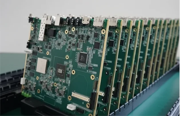
Confirm whether the package mix, board, materials, inspection, and test plan fit one manufacturable routeHilPCB supports single- and double-sided SMT assembly for engineering prototypes, first articles, NPI and pilot builds, and repeat production. The route can cover customer-supplied kits, partial-turnkey procurement, or full-turnkey component sourcing. Standard production includes 0201 packages and 0.4 mm pitch; 01005/008004 parts, 0.2–0.25 mm BGA or CSP pitch, unusually large boards, and difficult double-sided populations require review of the released design.
Can we assemble your design? Send Gerber or ODB++, the BOM with manufacturer part numbers, CPL or pick-and-place data, assembly drawings, quantity, sourcing responsibility, and inspection or test requirements. Engineering checks file revisions, land patterns, polarity, DNI/DNP rules, panel support, thermal mass, MSL handling, rework access, and acceptance criteria before confirming capability and schedule.
Use through-hole assembly when connectors, transformers, relays, or other inserted parts drive the process. Use turnkey assembly when BOM ownership and sourcing are the main requirement, or box build assembly when enclosure, cable, firmware, and final system integration are included.
- Prototype, first-article, NPI, pilot, and repeat-production routes
- Single- and double-sided SMT with mixed-technology review
- 0201 standard; 01005 and 008004 by advanced-route review
- Consigned, partial-turnkey, and full-turnkey material models
- Inspection and test scope agreed before production release
🚀 Quick Quote Request
📋 Get Full Capabilities
BGA, QFN, Fine-Pitch and Double-Sided SMT Assembly Review
Package geometry and board construction determine the print, placement, reflow, inspection, and rework planBGA, CSP, QFN, LGA, bottom-terminated, miniature, moisture-sensitive, polarity-sensitive, and heavy components are reviewed as a package system rather than by package name alone. Engineering checks the land pattern, solder-mask clearance, stencil aperture, paste alloy, via-in-pad condition, thermal-pad design, board support, reflow window, and available rework access.
For double-sided SMT, the review also covers side sequence, bottom-side component mass, second-pass thermal exposure, support tooling, and inspection access. A placement machine specification such as ±25 μm on a standard platform or ±8 μm on an advanced platform describes equipment reference performance; it is not a guaranteed finished-board placement tolerance. The quoted route confirms what is practical for the actual board and component population.
SPI can check paste deposits before placement, AOI can inspect visible assembly conditions, and selected X-ray can evaluate agreed hidden-joint locations. ICT, flying probe, boundary scan, programming, and functional test are separate options based on test access, customer data, fixtures, and the approved test plan.
- Land pattern, stencil, paste, finish, support, and rework review
- BGA/QFN/LGA/CSP hidden-joint inspection planning
- Double-sided side sequence and second-reflow exposure review
- MSL, floor-life, dry-storage, baking, and polarity controls
- AOI and X-ray scope matched to visible and hidden-joint risk
SMT PCB Assembly Technical Capabilities
Standard screening values and advanced routes that require review of the released assembly package
| Parameter | Standard Capability | Advanced Capability | Confirmation Basis |
|---|---|---|---|
Build Stage | Prototype, first article, NPI, pilot, repeat production | Higher-volume repeat programs by capacity review | Quantity, forecast, revision, panel, and release gates |
Service Model | Consigned / kitted and partial-turnkey | Full-turnkey and mixed-supply by BOM-line ownership | AVL, alternates, supplied parts, and substitution authority |
Minimum Component Size | 0201 (0.6 × 0.3 mm) | 01005 / 008004 by advanced-route review | Actual package, land pattern, stencil, finish, and inspection plan |
Fine Pitch | 0.4 mm pitch | 0.2–0.25 mm BGA/CSP pitch by review | Package data, pad and mask geometry, via condition, and rework access |
Placement Equipment Reference | ±25 μm at 3σ machine specification | ±8 μm at 3σ advanced-platform specification | Equipment reference, not a universal finished-board tolerance |
Board Size | Up to 510 × 460 mm | Up to 800 × 600 mm by line and support review | Finished panel, thickness, warpage, mass, rails, and handling |
Board Thickness | 0.4–6.0 mm | 0.2–10.0 mm by conveyor and support review | Board construction, support-pin access, warpage, and component mass |
SMT Sides and Packages | Single- and double-sided SMT; BGA, QFN, LGA, CSP | Dense double-sided, PoP, SiP, and rework-sensitive routes by review | Side sequence, thermal exposure, support, inspection, and rework plan |
Inspection | 3D SPI and 2D/3D AOI | Selected X-ray / AXI for agreed hidden-joint risks | Package-risk list, sample plan, locations, and acceptance basis |
Programming and Test | Visual and customer-defined electrical checks | ICT, flying probe, boundary scan, programming, and FCT | Test data, access, fixture, firmware, limits, and result format |
Solder and Reflow | Lead-free SAC alloys and forced-convection reflow | SnPb, low-temperature alloy, nitrogen, or special thermal route by review | Paste, component limits, board mass, reliability, and residue requirements |
Quality Systems | ISO 9001; IPC-A-610 / J-STD-001 workmanship by order | IATF 16949 or ISO 13485 program controls within applicable certified scope | Confirm legal entity, site, certificate scope, revision, and product class |
Prototype Schedule | 3–5 working days after release readiness | 24–48 hour expedite for eligible builds | Quoted after DFM, material, stencil, program, test, and capacity review |
Ready to start your PCB project?
Whether you need simple prototypes or complex production runs, our advanced manufacturing capabilities ensure excellent quality and reliability. Get your quote within 30 minutes.
SMT Assembly RFQ Requirements
A quote must define both the physical assembly and the release evidence. Send the following package so engineering can answer feasibility, price, schedule, material risk, and test scope without guessing.
- Board data: Gerber or ODB++, drill data, stackup when relevant, and panel requirements
- Assembly data: BOM with MPNs and approved alternates, CPL or pick-and-place, assembly drawings, polarity references, and DNI/DNP rules
- Commercial scope: quantity, build stage, forecast, consigned/partial/full-turnkey responsibility, and target schedule
- Quality scope: target IPC class and revision, first-article approval, SPI/AOI/X-ray scope, programming, ICT/FCT, cleaning, traceability, and required reports
- Risk notes: fine-pitch, BGA/QFN/LGA/CSP, MSL, bottom-side mass, tall or heavy components, sensitive parts, and rework restrictions
SMT Assembly Process: Printing, Placement, Reflow and Inspection
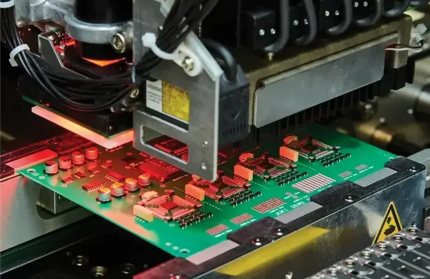
The controlled route is release review -> stencil and support planning -> solder paste printing -> SPI when specified -> component placement -> reflow -> AOI -> selected X-ray -> programming and test -> final release. Each gate resolves a different risk: data conflicts before programming, paste transfer before placement, package orientation before volume production, thermal compatibility before reflow, and acceptance evidence before shipment.
Reflow settings are developed around the selected paste, board thermal mass, component temperature limits, hidden-joint packages, and double-sided exposure. Profile records, machine data, inspection results, and test outputs are retained or delivered only as defined by the order, quality agreement, and quoted evidence package.
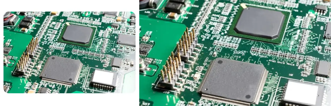
SPI, AOI, X-Ray, ICT and Functional Test Coverage
- SPI: checks paste height, area, volume, alignment, insufficient deposit, and bridging risk before placement; it does not verify the final solder joint or electrical function.
- AOI: checks visible presence, polarity, offset, tombstoning, lifted leads, and visible solder conditions; it cannot see every hidden joint.
- Selected X-ray: evaluates agreed BGA, QFN, LGA, CSP, or other hidden-joint locations for alignment, bridges, opens, solder distribution, and voiding evidence; locations, sampling, and acceptance limits must be defined.
- ICT or flying probe: checks accessible nets and customer-defined electrical limits when test data and access support the method.
- Functional test: verifies the behavior defined by the supplied firmware, procedure, fixture, connections, limits, and acceptance criteria.
Consigned, Partial-Turnkey and Full-Turnkey Component Supply
Consigned or kitted assembly fits programs where the customer owns component procurement and sends a complete, verified kit. Partial-turnkey divides BOM-line ownership between the customer and HilPCB. Full-turnkey assembly places sourcing responsibility with HilPCB under the approved BOM, AVL, alternates, and substitution rules.
For each model, define excess allowance, moisture-sensitive handling, packaging condition, lifecycle constraints, date/lot restrictions, alternates, and who can approve a substitution. No alternate should enter the released build without the approval authority defined for the order. See turnkey PCB assembly for the broader procurement workflow.
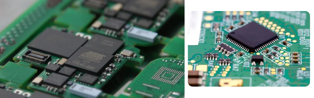
SMT First-Article and Prototype-to-Production Handoff
A prototype proves that a board can be built; NPI establishes a controlled route that can be repeated. Before moving to pilot or repeat production, freeze the approved revision, BOM and CPL, stencil, placement program, side sequence, reflow route, inspection criteria, test procedure, approved alternates, rework disposition, and required records.
First-article scope can include orientation confirmation, build photos, inspection results, X-ray images at selected packages, programmed-device status, electrical or functional results, and open-issue disposition. The exact record package is quoted because a first article, inspection sample, and full report pack are different deliverables.
SMT Assembly Quality Records and Traceability Deliverables
Available production controls can link the released revision, work order or traveler, material lots, machine programs, inspection results, nonconformance disposition, and test status. The required linkage depends on the program and applicable system scope; it should not be assumed to be identical for every order.
List required deliverables in the RFQ and quality agreement. Options can include a first-article record, material certificate or CoC where available, reflow profile record, SPI/AOI summary, selected X-ray images, programming record, ICT/FCT result, lot or serial traceability, and certificate of conformance. HilPCB confirms record availability, retention, format, and delivery at quotation.
SMT PCB Assembly for Industrial, Automotive and Medical Electronics
Industrial controls, communications hardware, IoT devices, automotive electronics, and medical equipment impose different material, cleanliness, traceability, inspection, and test requirements. State the end-use environment, regulatory or customer specification, target IPC class, expected service conditions, and documentation needs during quotation. Program controls under IATF 16949 or ISO 13485 apply only within the relevant certified scope and agreed project route.
For dense high-speed designs, coordinate assembly review with high-speed PCB manufacturing. For RF packages and laminate constraints, use high-frequency PCB manufacturing. These reviews help align fabrication tolerances, surface finish, via structure, thermal behavior, assembly access, and test strategy before release.
SMT Engineering Examples for Route Planning
These are common engineering scenarios that HilPCB can review and route according to the released design, package mix, material set, inspection plan, and test requirements. Use the same questions during RFQ review: what is the package risk, which process gate controls it, and which evidence must be delivered?
High-speed compute and server boards. Dense BGA populations, high thermal mass, and fast interfaces require package-land-pattern review, stencil and support planning, a thermal profile matched to component limits, and agreed AOI/X-ray and electrical coverage. See the AI server motherboard assembly guidance for the design-to-assembly risk chain.
Data-center optical modules. Compact QSFP-DD or OSFP assemblies combine fine-pitch devices, thermal constraints, firmware or programming, and interface testing. A practical release package ties the BOM and revision to placement, reflow, inspection, programming, and any boundary-scan or functional result. See the data-center optical-module assembly guidance for the evidence questions to resolve.
5G/6G and mmWave modules. BGA void risk, RF laminate transitions, thermal paths, and hidden-joint inspection must be reviewed together. The route may combine stencil aperture work, SPI, a profile or special reflow review, selected X-ray, and RF or functional acceptance defined by the customer. See the mmWave BGA reflow guidance for the risk model.
Frequently Asked Questions
What files are required for an SMT assembly quote?
Can HilPCB assemble 01005 components and fine-pitch BGA or CSP packages?
How are BGA and QFN solder joints inspected?
What is the prototype SMT assembly lead time?
Do you support consigned and turnkey SMT assembly?
What SMT inspection, test, and traceability records can be supplied?
Experience Advanced PCB Manufacturing Excellence
From simple prototypes to complex production runs, our world-class factory delivers superior quality, fast turnaround and competitive pricing. Join thousands of satisfied customers who trust us with their PCB manufacturing needs.