
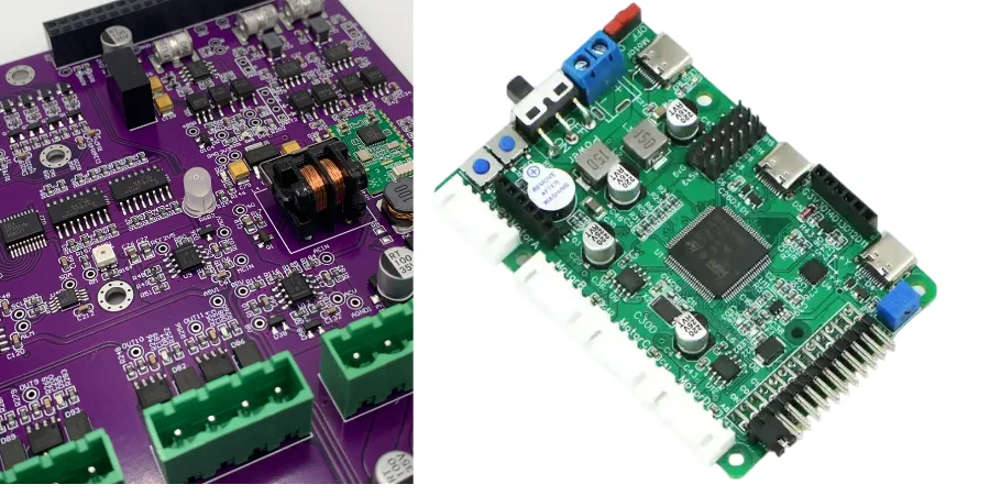
Boundary-Scan/JTAG robot controller safety validation is no longer a niche lab topic. On an industrial robot safety controller PCB, the test strategy has to prove that dual-channel logic, E-Stop paths, watchdog reactions, and production workmanship all support the same functional safety objective. In practice, Boundary-Scan/JTAG robot controller safety work sits between design-for-test, certification evidence, and volume manufacturing discipline.
That is why JTAG should not be treated as a debug connector added at the end. For robot controller safety programs targeting IEC 61508 or ISO 13849, JTAG is most valuable when it is planned early, mapped to diagnostic coverage goals, and combined with assembly validation, traceability, and field-service access.
Why Boundary-Scan/JTAG Matters for Robot Controller Safety
Industrial robot controllers have two problems at the same time: they must react safely to faults, and they must stay testable even as boards become denser, more integrated, and harder to probe physically.
Boundary-Scan/JTAG helps because it can:
- Verify digital interconnect integrity on safety-critical MCU, FPGA, CPLD, and interface nets.
- Support repeatable fault-injection workflows for dual-channel cross-monitoring logic.
- Improve diagnostic coverage evidence beyond what software self-test can prove by itself.
- Reduce reliance on physical probing for hidden joints and high-pin-count packages.
- Stay useful from EVT through field maintenance when the interface is intentionally preserved.
The result is not that JTAG replaces every other test. The value is that it gives robot safety teams a controlled, hardware-level method to prove specific fault-detection assumptions before those assumptions reach certification review or mass production.
Key Design and Validation Reference Table for Robot Safety PCBs
The table below summarizes common review items for robot controller safety programs. Final limits still need to match the risk analysis, target SIL/PL level, channel architecture, and the device set actually included in the JTAG chain.
| Validation item | Typical review point | Why it matters |
|---|---|---|
| Safety architecture | Dual-channel or monitored single-channel design is reviewed against the required risk reduction target | JTAG test cases should map to the actual safety concept, not a generic board checklist |
| JTAG device coverage | MCU, FPGA, CPLD, safety monitor, and other critical digital devices are reviewed early for chain inclusion | Missing a key device often removes the most valuable observability path |
| BSDL readiness | Vendor BSDL files should be collected and checked before vector development starts | Incomplete or wrong BSDL data delays DFT and production test release |
| Fault injection scope | Inter-channel links, E-Stop paths, watchdog/reset paths, and feedback loops are typically prioritized | These paths directly affect diagnostic coverage and fault reaction claims |
| Fault reaction time evidence | Injected events and safe-state responses should be measured with a repeatable method | Safety timing claims need evidence, not only software expectations |
| Post-assembly coverage | JTAG is usually combined with AOI, X-ray, flying probe, or FCT based on package density | No single method covers every defect mode on a safety PCB |
| Traceability | Serial number, revision, JTAG log, and repair history should stay linked | Certification and root-cause analysis depend on auditable records |
If your team has not yet frozen the scan-chain topology, BSDL set, and safety-related test ownership, it is better to review them before layout release than after the first coverage gap appears in validation.
Dual-Channel Diagnostics and Fault Injection Strategy
The most important use of JTAG on a robot safety controller is usually not board bring-up by itself. It is proving that redundant channels and cross-check logic behave correctly when one side is wrong.
Typical review points include:
- Whether Channel A and Channel B interconnects can be checked for opens, shorts, and unintended bridges after assembly
- Whether fault injection is defined as a structured validation task instead of an ad hoc lab exercise
- Whether periodic diagnostic tests cover the same paths that the FMEDA or safety analysis claims are protected
- Whether feedback signals from relays, contactors, drivers, or safety I/O are part of the observable test path
For robot controllers, those tests are often paired with fixture planning and complementary electrical coverage. Teams that need a broader production strategy usually review Boundary-Scan/JTAG for industrial robotics control, ICT/FCT fixture design for industrial robotics control, and flying probe test for industrial robotics control PCB reliability together rather than as isolated decisions.
Fault Reaction Time, Watchdog Paths, and Safe-State Verification
Robot safety validation is not only about finding shorts and opens. The harder question is whether the controller reaches the safe state within the required time after a dangerous fault is introduced.
JTAG is useful here because it can create repeatable pin-state conditions and help structure the validation sequence around:
- Safety input transitions that should trigger a defined shutdown path
- Inter-channel disagreement events that should be detected by cross-monitoring logic
- Watchdog, reset, enable, and fault-feedback paths that must drive a safe output condition
- Repeatable hardware states that can be correlated with oscilloscope or logic-analyzer timing measurements
The important engineering discipline is to avoid overstating what JTAG alone proves. In many programs, JTAG provides the controllable hardware stimulus while external timing capture confirms the end-to-end delay. That combination is much stronger than relying on firmware logging only, especially when the claim is tied to IEC 61508 or ISO 13849 review.
DFT Architecture, BSDL Management, and Scan-Chain Planning
Good robot controller safety validation starts at schematic and layout review, not after the first prototype fails coverage goals. JTAG DFT planning usually needs to lock three things early:
- Chain topology: Partition chains by function or power domain when that improves fault isolation, test time, or service access.
- Access strategy: Keep the TAP interface reachable for prototype validation, production fixtures, and approved maintenance workflows.
- Manufacturing compatibility: Make sure chain routing, reference planes, and connector placement still fit the actual board architecture and assembly flow.
This matters even more on dense multilayer PCB structures and lamination plans where safety logic, communications, and power-management sections share the same board. When the project also needs controlled assembly release, it helps to align DFT expectations with the manufacturing partner before the first build instead of after a failed validation round.
Production Validation: From EVT/DVT/PVT to Coated or Potted Assemblies
The value of Boundary-Scan/JTAG increases when it is used as part of a staged production-quality plan instead of a one-time engineering test.
Common checkpoints include:
- EVT/DVT/PVT: use JTAG to support bring-up, structural checks, and repeatable safety-path validation during NPI.
- First article and process release: compare early production results with approved vectors and expected fault responses before scaling.
- Volume production: combine JTAG with SMT assembly process control, turnkey assembly execution, and defect-screening methods such as BGA X-ray inspection.
- High-reliability finishing steps: keep JTAG available when conformal coating or potting reduces physical access after assembly.
- Field diagnostics: preserve the approved service path so maintenance teams can read state, isolate faults, or verify board replacement safely.
For safety-critical workmanship expectations, it is also useful to align release criteria with IPC Class 3 PCB manufacturing practices.
Common Questions
Is JTAG enough by itself for robot safety PCB validation?
No. JTAG is powerful for structural coverage, controlled pin access, and repeatable diagnostic tests, but safety programs still need risk analysis, functional testing, and the right complementary inspection methods for the package mix and failure modes involved.
When should JTAG be planned in a robot controller project?
At schematic and layout definition, not after prototype assembly. By that point, missing devices, poor connector access, or weak chain partitioning are already expensive to fix.
Can JTAG still help after conformal coating or potting?
Yes, if the access path is intentionally preserved. That is one reason JTAG is valuable in harsh-environment robot control products where post-process probing becomes difficult.
What is the most common mistake teams make?
Treating JTAG as a debug convenience rather than a mapped safety-validation asset. If test cases are not tied to diagnostic coverage claims, fault reaction objectives, and production release criteria, much of the real value is lost.
Next Steps
If your robot controller safety project needs JTAG DFT review, scan-chain planning, or production-test alignment before the next build, contact the engineering team or request a manufacturing and assembly review. It is cheaper to close test-coverage gaps before certification evidence and fixture development start moving in parallel.