
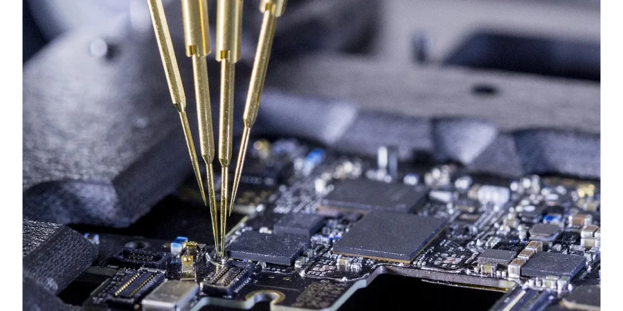
Flying probe test is a fixtureless electrical test method that moves programmable probes between accessible PCB targets. It is especially useful for prototypes, high-mix production, and changing medical electronics because the test program can be revised without rebuilding a bed-of-nails fixture.
Flying probe is one layer of evidence, not a medical-device compliance test. It can find defined electrical defects, but it does not by itself prove IEC 60601 safety, ISO 10993 biological safety, EMC, software behavior, diagnostic performance, or finished-device reliability.
Key Takeaways
- Distinguish bare-board flying probe from assembled-PCBA flying probe; they use different source data, stimuli, limits, and defect models.
- Specify coverage by testable fault and node, not by saying “100% tested.”
- Use flying probe early when revisions are frequent, then compare cycle time and coverage with ICT, boundary scan, and functional test before volume release.
- A probe can measure continuity or resistance across an accessible barrier, but it does not inspect creepage geometry or certify leakage-current compliance.
- Test before conformal coating when coating blocks access, then perform the post-coating and finished-equipment tests required by the product risk plan.
- Use X-ray or another validated inspection for hidden BGA joints; an electrical pass does not measure voiding or joint geometry.
- Link every result to the board revision, test-program revision, limits, equipment status, operator/fixture state, and unit or lot identity.
Table of Contents
- What can flying probe test detect?
- What flying probe cannot prove
- Bare-board vs assembled-board flying probe
- Match each medical risk to the right evidence
- Design test access before layout release
- Choose flying probe vs ICT vs functional test
- Build an EVT DVT PVT test migration plan
- Test around coating, BGA, flex, and high voltage
- Define coverage, limits, and records
- Common test escapes and first evidence
- Flying probe test RFQ checklist
- Reference standards and responsibility boundaries
- How HILPCB can support the test package
- Frequently asked questions
What Can Flying Probe Test Detect?
Coverage depends on board state, tester configuration, access, program quality, and approved limits.
Bare-board test compares manufactured connectivity with a supplied netlist. It can detect opens, unintended shorts and specified resistance/isolation conditions. It cannot reveal a wrong source netlist.
Assembled-board systems may add component values, junction checks, pin-open techniques, optical inspection, programming, boundary scan, powered measurements, or limited functions. Require each enabled technique in the quotation.
| Defect or condition | Flying probe potential | Required definition |
|---|---|---|
| Open net or unintended short | Strong for accessible, modeled nets | Reference netlist, thresholds, isolation strategy and exclusions |
| Resistor/capacitor value | Often possible in circuit | Tolerance, guarding/modeling, parallel paths and component state |
| Diode or semiconductor junction | Possible for supported accessible nodes | Stimulus, polarity, limit and safe voltage/current |
| Missing/open IC pin | Possible with supported non-contact or vectorless methods | Device library, access, sensitivity and validation samples |
| Firmware programming | Possible on equipped systems | Image hash, interface, security state and verification method |
| Powered functional behavior | Possible only with configured power and instruments | Safe power-up sequence, loads, limits, interlocks and coverage |
| Hidden solder-joint geometry | Not directly measured | X-ray, cross-section, process validation or other suitable evidence |
What Flying Probe Cannot Prove
IEC 60601-1 addresses basic safety and essential performance of medical electrical equipment. Compliance depends on the finished equipment or system, its applied parts, insulation architecture, enclosure, power source, software, risk controls, labeling, and required collateral or particular standards. A PCB continuity test is only supporting manufacturing evidence.
Flying probe does not determine creepage and clearance from geometry, material group, pollution, altitude, working voltage, transient stress, or means-of-protection requirements. Those are design and inspection tasks. Nor is a routine low-voltage resistance measurement equivalent to dielectric-strength, protective-earth, touch-current, patient-leakage, or other equipment-level safety tests.
ISO 10993-1 frames biological evaluation within a risk-management process for a medical device. The evaluation follows the nature and duration of body contact and the final contacting materials and processes. A PCB buried inside a sealed enclosure is not assessed the same way as an exposed wearable electrode. Conformal coating is not automatically a validated biocompatibility barrier.
Bare-Board vs Assembled-Board Flying Probe
| Test stage | Primary input | Useful detections | Important blind spots |
|---|---|---|---|
| Bare PCB | Gerber/ODB++/IPC-2581, IPC-D-356 or approved netlist, drill and test specification | Opens, shorts and specified electrical characteristics | Wrong design netlist, latent material defects outside the test, impedance without a defined method/coupon |
| Unpowered PCBA | BOM, centroid, schematic/netlist, assembly data, approved limits | Shorts, opens, some values, junctions, pin connectivity and component presence with supported methods | Firmware, dynamic behavior, inaccessible nodes, many parallel-path ambiguities |
| Powered PCBA on flying prober | Power sequence, current limits, instruments, test vectors and safety controls | Selected rails, programming, communications and limited functions | Full clinical use, complete performance, EMC, thermal/mechanical use conditions |
| Finished medical device | System test specification and risk controls | Product functions and safety/performance evidence within the validated setup | Anything outside the declared test scope and use conditions |
The bare-board netlist, assembly program, firmware, and system test specification must remain separate, versioned objects.
Match Each Medical Risk to the Right Evidence
Use this matrix to keep claims within each method's measurement domain.
| Risk or claim | Appropriate evidence layer | Flying probe role | Evidence owner |
|---|---|---|---|
| PCB open/short | Bare-board electrical test against approved netlist | Primary or complementary method | PCB fabricator within purchase specification |
| Wrong/missing component or solder bridge | SPI/AOI/X-ray plus electrical test as applicable | Detects accessible electrical effects and supported component faults | PCBA manufacturer/test engineering |
| BGA voiding or hidden-joint geometry | X-ray/process qualification; destructive analysis when required | May detect an electrical open/short, not void percentage or joint shape | Assembly process owner |
| Creepage/clearance | Insulation design review, CAD rules and dimensional inspection | May test connectivity/isolation under defined conditions only | Device design and safety engineering |
| Dielectric strength/leakage current | Validated safety-test setup on the specified assembly/equipment state | Only if a dedicated approved setup is integrated; not assumed | Legal manufacturer/product test owner |
| EMC immunity/emissions | IEC 60601-1-2 or applicable product-level EMC plan | Can screen manufacturing faults before EMC test | Device manufacturer/laboratory |
| Biocompatibility | ISO 10993 biological evaluation plan for final contact materials/processes | No direct biological evidence | Device manufacturer/biological safety team |
| Essential performance | Risk-based system verification under normal and fault conditions | Supports board-level fault screening | Device manufacturer/system verification |
| Software/firmware correctness | Controlled build, programming verification and software/system tests | Can program and verify a hash where configured | Software and device manufacturer |
Design Test Access Before Layout Release
Fixtureless testing still needs accessible, robust targets and a pre-release node-level access report.
- Map critical rails, grounds, communication buses, safety-related monitoring, programming and debug nodes to accessible targets.
- Provide target diameter, mask opening, spacing, component-height keep-outs, probe angle, side access and allowable witness-mark rules from the selected equipment.
- Avoid placing the only access under shields, batteries, displays, stiffeners, enclosures, coating, adhesive or inaccessible flex bends.
- Define safe discharge for capacitors and high-voltage nodes; probes and operators must not encounter stored energy unexpectedly.
- Consider board support and probe force for thin rigid-flex or wearable assemblies to prevent deflection and intermittent contact.
- Reserve stable datum/fiducial information so vision alignment follows the correct revision.
- Identify nodes that cannot be probed and assign boundary scan, connector test, functional stimulus, or justified exclusion.
Coverage is the share of defined faults a validated program can detect—not the share of nets with visible pads.
Choose Flying Probe vs ICT vs Functional Test
| Method | Best fit | Strength | Main tradeoff |
|---|---|---|---|
| Flying probe | Prototype, NPI, high mix, lower volume, frequent ECO | Low fixture dependency, flexible programming, useful diagnostics | Serial motion and access can limit throughput and coverage |
| ICT/bed of nails | Stable design and higher volume | Fast parallel access and repeatable production flow | Fixture NRE, lead time, maintenance and ECO cost |
| Boundary scan | Digital designs with compliant devices and chains | Tests otherwise inaccessible interconnects; supports programming | Requires architecture, device support and developed vectors |
| Functional test | Required product behavior and interfaces | Exercises real functions and performance limits | Fault localization may be weak; fixture/software validation is substantial |
| AOI/SPI/X-ray | Process and structural defect detection | Sees defect classes electrical tests may miss | Does not prove complete electrical function |
Layer methods: flying probe for prototype diagnosis, boundary scan for supported inaccessible digital links, and functional test for behavior. Stable volume may justify ICT or a hybrid fixture.
Build an EVT DVT PVT Test Migration Plan
| Phase | Test objective | Flying probe use | Exit evidence |
|---|---|---|---|
| EVT | Find design and assembly faults quickly | Broad diagnostics, engineering measurements, programming and revision comparison | Known-fault detection, updated DFT map, defect log and corrected design |
| DVT | Verify design outputs and risk controls | Controlled regression screen before system verification | Frozen fault model, limits, repeatability and correlation to system tests |
| PVT | Prove production process and records | Pilot production screen and escape analysis | Cycle time, false-call/escape data, operator flow, traceability and control plan |
| Production | Sustain required coverage economically | Continue, automate, sample, or migrate based on validated evidence | Approved test strategy, maintenance, golden units, change triggers and monitoring |
Before migration, compare coverage, access, cycle time, NRE, design life, diagnostics, maintenance, and escape cost. Reassess the program after every relevant ECO.
Test Around Coating, BGA, Flex, and High Voltage
Test before conformal coating when the coating prevents probe contact or makes repair destructive. Then perform any post-coating visual, insulation, environmental, and finished-device safety tests required by the risk and verification plans. Define masking, cleanliness, cure, thickness and rework controls separately.
Electrical testing can detect some BGA opens/shorts, but void claims require X-ray or process evidence. Room-temperature passes may miss faults under flex, vibration, temperature, or strain.
High-voltage medical imaging boards require extra controls: maximum safe probe stimulus, current limiting, discharge verification, interlocks, barrier identification, probe spacing, fixture insulation, and separation between manufacturing screen and formal safety test. Wearable flex assemblies need strain control, contact-safe finishes where exposed, and a test state that represents the intended bend or connector condition when relevant.
Define Coverage, Limits, and Records
Connect each requirement to a method, stimulus, limit, guard, failure code, retest policy, and record. Validate with known-good and known-fault units where practical.
Retain at least:
- product/PCB/PCBA revision and serial or lot identity;
- test program, library, firmware and limit-set revisions;
- tester, option/instrument configuration, calibration/status and software version;
- result by test, measured value where useful, failure code, timestamp and operator/automation identity;
- retest, repair, deviation, disposition and linkage to the original failure;
- coverage report with inaccessible nodes, disabled tests, assumptions and approved exclusions.
Common Test Escapes and First Evidence
| Escape or symptom | Plausible cause | First evidence |
|---|---|---|
| Wrong board passes | Program/netlist matches an obsolete revision | Package hash, program source and revision mapping |
| Intermittent false failures | Poor target, board flex, contamination, probe wear or alignment | Contact repeatability, probe marks, force/support and maintenance log |
| BGA defect missed | Node inaccessible, parallel path, vectorless limit, or structural defect without electrical effect | Access/coverage report, X-ray and known-fault validation |
| Safety test later fails | Flying probe was mistaken for dielectric/leakage validation | Test methods, voltage/current setup and equipment-state definition |
| Failures appear after coating | Pre-existing contamination, coating defect, cure/rework issue or blocked access | Pre/post-coat records, cleanliness and coating inspection |
| Field fault despite electrical pass | Environmental, software, sensor, connector, mechanical or use-condition failure outside scope | Risk file, system logs, returned-unit analysis and test boundary |
Flying Probe Test RFQ Checklist
Product and risk context
- bare board or PCBA, medical imaging/wearable function, revision, quantities and NPI phase;
- critical circuits, safety-related monitoring, stored energy, high voltage and prohibited stimuli;
- applicable product standards, risk controls, acceptance class and traceability depth.
Manufacturing and test data
- Gerber X2/ODB++/IPC-2581, approved netlist, stackup and fabrication drawing;
- BOM/AVL, centroid, schematic, assembly drawing, DNP/variant data and firmware hash;
- test-point map, accessible sides, target rules, keep-outs, board support and coating state;
- fault model, test list, stimuli, limits, guarding, discharge and interlock requirements.
Supplier response and evidence
- tester model/configuration and enabled electrical, optical, thermal, programming or boundary-scan methods;
- node/fault coverage, inaccessible points, assumptions, disabled tests and proposed complementary methods;
- program-development, golden-unit, correlation and known-fault validation plan;
- cycle time, lot/sample coverage, retest/repair flow, calibration and maintenance status;
- result format, serial/lot linkage, record retention, change control and program ownership;
- exceptions separating PCB/PCBA manufacturing evidence from finished-device compliance.
Reference Standards and Responsibility Boundaries
Applicable references may include:
- IEC 60601-1, medical electrical equipment basic safety and essential performance
- IEC 60601-1-2, electromagnetic disturbances for medical electrical equipment
- applicable IEC 60601 particular standards for the equipment type
- ISO 10993-1, biological evaluation within a risk-management process
- ISO 14971, medical-device risk management
- ISO 13485, medical-device quality management systems where contractually applicable
- IPC-9252, electrical testing of unpopulated printed boards
- IPC-2221, IPC-2223, IPC-6012 and IPC-6013 as applicable to rigid and flexible boards
- IPC-A-600, J-STD-001 and IPC-A-610 for board/assembly acceptance as invoked
Confirm editions, jurisdictions, product classification and contractual clauses with the legal manufacturer and qualified specialists. A PCB/PCBA supplier can provide contracted manufacturing and test records; the legal manufacturer owns the device risk management, regulatory strategy, essential performance, biological evaluation, software, product verification and final release.
How HILPCB Can Support the Test Package
HILPCB can review test access and manufacturing scope for dense HDI PCB or wearable rigid-flex PCB designs. For assembled builds, use turnkey assembly to define the exact inspection, flying-probe, programming and functional-test responsibilities that will appear in the quotation.
Send the approved netlist, revision-controlled manufacturing data, BOM/CPL, schematic, test-point map, fault model, limits, firmware, coating state and required records. Ask HILPCB to return coverage gaps, assumptions, equipment/configuration, complementary inspection, cycle time and change-control terms through the quote page.
Frequently Asked Questions
Can flying probe test certify a medical PCB to IEC 60601?
No. It can provide PCB or PCBA manufacturing evidence for defined electrical faults. IEC 60601 compliance depends on the finished medical electrical equipment, risk controls, insulation, enclosure, software, essential performance and required system tests.
Can flying probe test verify biocompatibility under ISO 10993?
No. Biological evaluation concerns the final device's body-contacting materials, processes, contact type and duration within risk management. Flying probe does not evaluate chemical or biological response.
Is flying probe always better than ICT for medical electronics?
No. Flying probe is attractive for changing designs and lower volumes; ICT can provide faster parallel testing for stable higher-volume products. Coverage, access, cycle time, NRE, lifecycle and diagnostics determine the choice.
Should a coated medical PCBA be flying-probe tested?
Normally the accessible electrical screen is completed before coating. Post-coating inspection and any required insulation, environmental, functional or finished-device safety tests still follow the approved risk and verification plans.
Does flying probe detect every BGA solder defect?
No. It may detect electrical opens or shorts on accessible paths, but hidden-joint shape, voiding and mechanically weak connections need suitable structural inspection and process validation.
Conclusion
Flying probe test is valuable in medical PCB NPI because it provides flexible, revision-friendly electrical evidence without a dedicated bed-of-nails fixture. Its value increases when every test has a defined fault, access path, stimulus, limit and record—and when product safety, EMC, biocompatibility and performance remain assigned to the correct validation layers.