
With the explosive growth of AI and high-performance computing (HPC) applications, the bottleneck of data processing has moved from the compute units themselves to the “last mile” of data transfer: die-to-die interconnects. HBM3 (High Bandwidth Memory 3) and its subsequent evolutions deliver extraordinary memory bandwidth, making them central to breaking this bottleneck. However, seamlessly integrating a powerful AI processor with HBM3 stacks requires a seemingly small yet mission-critical component: the interposer. Guaranteeing exceptional HBM3 interposer PCB quality is no longer an option, but the foundational stone that determines whether the entire AI chip can operate stably and efficiently. As an engineer focused on thermal interfaces and tolerance control, I deeply understand that in a micron-scale world, even the slightest deviation can cause a cliff-edge drop in performance or outright system failure.
This article will examine the core elements that determine HBM3 interposer PCB quality, from high-speed signal integrity and harsh thermal management to complex power delivery networks and manufacturing processes, revealing the challenges and solutions in mastering this advanced technology. Understanding how HILPCB can help optimize your AI interconnect/substrate design will be a critical step toward your success.
Why does HBM3 interconnect place unprecedented requirements on interposer PCBs?
Every iteration of HBM technology signifies an exponential growth in data transfer rates and channel density. From HBM2e to HBM3, the data rate doubles, pins per stack exceed 1024, and total bandwidth effortlessly breaches the TB/s level. This performance leap translates directly into extreme requirements for the HBM3 interposer PCB that carries and connects these signals.
First, the physical scaling challenge is brutal. The interposer must accommodate tens of thousands of micro-bumps within a tiny area (typically a few hundred square millimeters) to connect the SoC and HBM chips above, while fanning out to connect to the package substrate below. The pitch of these connection points has shrunk to the micron level, imposing requirements on routing density and manufacturing precision that rival semiconductor wafer processes.
Second, the electrical performance requirements have reached new heights. At signal rates exceeding 6.4 Gbps, every micron-scale trace on the interposer must be treated as a precision transmission line. Any minute geometric deviation or inconsistency in material dielectric properties will trigger severe signal attenuation, reflection, and crosstalk, directly impacting the correctness of data transmission. Therefore, crafting a qualified low-loss HBM3 interposer PCB becomes a core objective in the early design stages.
Finally, the interposer is no longer just an electrical connection platform. Located at the heart of the entire 2.5D packaging structure, it is a critical hub for heat and power transfer. The massive heat generated by the AI die and HBM stacks must be efficiently conducted away through it. Simultaneously, stable and clean current must be precisely delivered through it to every transistor. This makes interposer design a complex systems engineering task involving the coupling of electrical, thermal, and mechanical multi-physics fields.
How do you ensure signal integrity (SI) in micron-scale routing?
At the ultra-high data rates of HBM3, Signal Integrity (SI) is the primary electrical metric determining HBM3 interposer PCB quality. Although the routing lengths on the interposer are short (usually in the millimeter range), their extreme density and speed make SI design exceptionally complex.
1. Precise Impedance Control: The impedance of HBM3 channels must be strictly controlled within a specified target range (e.g., 50 ohms). With line widths under 10 microns, any slight etch error, dielectric thickness fluctuation, or copper thickness variation will cause impedance deviation. This requires manufacturers to adopt advanced manufacturing processes, such as mSAP (modified Semi-Additive Process) or SAP (Semi-Additive Process), to achieve precise control over trace geometry. Concurrently, materials with extremely stable Dielectric Constant (Dk) and Dissipation Factor (Df) across the entire frequency range must be selected.
2. Strict Crosstalk Management: Thousands of signal lines run in parallel with minimal spacing between them, making crosstalk a major threat. The design must suppress Near-End Crosstalk (NEXT) and Far-End Crosstalk (FEXT) through routing optimization, adding ground shielding, and precisely controlling trace spacing. Advanced SI simulation tools are essential early in the design phase to predict and evade potential crosstalk pitfalls.
3. Minimizing Insertion Loss and Return Loss: Signals attenuate during transmission due to dielectric and conductor losses, known as Insertion Loss. Choosing materials with ultra-low Df values, such as Ajinomoto Build-up Film (ABF) or similar high-performance dielectrics, is key to creating a low-loss HBM3 interposer PCB. Impedance discontinuities (like vias and pads) cause signal reflection, or Return Loss. Optimizing via structures, pad geometry, and connections to micro-bumps is vital for maintaining signal quality. In this regard, a profound understanding and application of high-speed PCB design principles are indispensable.
Interposer Substrate Material Performance Comparison
| Performance Metric | Standard FR-4 | High-Speed Laminates (e.g., Megtron 6) | ABF Build-up Film |
|---|---|---|---|
| Dielectric Constant (Dk @10GHz) | ~4.5 | ~3.6 | ~2.8 - 3.2 |
| Dissipation Factor (Df @10GHz) | ~0.020 | ~0.002 | ~0.001 - 0.002 |
| Min Line Width/Space | > 75µm / 75µm | ~ 25µm / 25µm | < 10µm / 10µm |
| Thermal Conductivity (W/m·K) | ~0.3 | ~0.6 | ~0.4 |
| Typical Application | Conventional PCBs | High-end server motherboards | HBM Interposers, IC Substrates |
What are the thermal management strategies under the massive power consumption of AI chips?
As a thermal interface design engineer, I must emphasize that thermal management is key to determining HBM3 interposer PCB reliability and long-term performance. An AI accelerator consuming hundreds or even over a thousand watts has a heat density comparable to a nuclear reactor. The interposer sits right at the center of this "thermal storm."
1. Highly Efficient Vertical Conduction Paths: The interposer itself must become an efficient heat dissipation channel. The design will heavily use Thermal Vias—tiny channels filled with conductive materials that act like miniature heat pipes—to rapidly conduct the heat generated by the chips to the package substrate and heatsink below. The density, diameter, and fill material of thermal vias directly affect cooling efficiency.
2. Thermal Properties of Materials: While organic interposers (based on materials like ABF) offer advantages in electrical performance and cost, their thermal conductivity is far lower than that of silicon interposers. To compensate, organic interposer designs often embed large continuous copper planes as thermal spreading layers. The thickness and continuity of these copper layers are critical for lateral heat spreading.
3. Thermal Interface Material (TIM) and Coplanarity/Warpage Control: Heat transfer efficiency depends heavily on each interface. From the HBM chip to the interposer, and then to the package substrate, each layer requires the use of high-performance Thermal Interface Materials (TIM). However, TIM performance relies on interface flatness and contact pressure. Interposer warpage is the natural enemy of thermal management. Even a few microns of warpage can lead to uneven TIM thickness, forming hotspots, and ultimately causing the HBM chip to throttle or sustain damage due to overheating. Therefore, controlling HBM3 interposer PCB quality, especially warpage, directly relates to the success or failure of the entire system's thermal management. Professional manufacturers like HilPCB PCB Factory (HILPCB) can control warpage within extremely tight tolerances through symmetric stackup design, strict lamination process control, and careful material selection.
How does Power Integrity (PI) affect HBM3 stability?
If signal integrity ensures the "clarity" of data transmission, then Power Integrity (PI) guarantees the stable "heartbeat" of the entire system's operation. When AI chips perform large-scale parallel computations, their current demands violently fluctuate in an instant, generating massive transient noise.
1. Ultra-Low-Impedance Power Delivery Network (PDN): The HBM3 interposer PCB must provide an extremely stable, low-impedance power delivery network for the SoC and HBM. This is usually achieved by designing multiple dedicated power and ground planes within the stackup. These planes act like a giant capacitor, capable of responding rapidly to transient current demands and suppressing voltage droop.
2. Carefully Designed Decoupling Network: To filter out high-frequency noise, a large number of decoupling capacitors must be placed on the interposer and package substrate. On the severely space-constrained interposer, Embedded Capacitance technology is sometimes used, integrating capacitance layers directly into the PCB stackup to minimize the current loop length and maximize decoupling efficiency.
3. Minimizing Loop Inductance: Current flows from the power plane to the chip, and returns through the ground plane, forming a loop. The smaller the inductance of this loop, the faster the transient response and the lower the voltage noise. During design, power and ground via placements must be carefully planned, keeping them as close together as possible to reduce the loop area. An excellent HBM3 interposer PCB design can achieve PDN impedance as low as the milliohm level within the target frequency range.
💎 Interposer PDN: Golden Rules for Advanced Process Power Distribution
Optimizing vertical interconnects between silicon interposers and substrates to eliminate chip core voltage fluctuations
Core Strategy: Deploy Deep Trench Capacitors (DTC) or micro-capacitor arrays as close to the chiplets' physical limits as possible. By boosting local charge storage capabilities, provide sub-nanosecond current compensation for GHz-level switching actions.
Core Strategy: Use TSV (Through-Silicon Via) arrays to construct short-range power paths. Optimize the width-to-length ratio of the RDL (Redistribution Layer) and compress the current loop area to the micron scale through tightly stitched, interleaved power/ground vias.
Core Strategy: Establish continuous power and ground reference planes across all layers. Use the exceptionally thin dielectric thickness of the interposer to generate massive Inter-plane Capacitance, offering an ultra-low-impedance return path for high-frequency noise.
Core Strategy: It is mandatory to perform full-link CPM (Chip Power Model) co-simulation from the chip down to the package base. Accurately predict SSN (Simultaneous Switching Noise) and DC IR-Drop, and optimize routing density under thermal stress constraints.
For high-compute chips, we provide high-precision RDL (Fine Pitch Line/Space) and Micro-bump manufacturing support. By precisely controlling interlayer dielectric thickness and copper pillar alignment accuracy, HILPCB assists you in building Interposer solutions with supreme power integrity, fulfilling the rigorous dynamic power demands of AI and HPC.
What are the key manufacturing processes that determine HBM3 Interposer PCB reliability?
Even the most perfectly designed blueprint requires top-tier manufacturing processes to become reality. HBM3 interposer PCB reliability depends directly on the precision and consistency of the manufacturing process. This has already exceeded the scope of traditional PCBs, leaning closer to the semiconductor packaging domain, which is why it is typically handled by specialized IC Substrate PCB manufacturers.
1. Fine-Line Fabrication: To achieve line widths/spaces below 10 microns, traditional subtractive processes are powerless. SAP (Semi-Additive Process) or mSAP must be employed. These processes construct traces via lithography and plating on a thin copper layer, achieving nearly vertical trace sidewalls and extremely high dimensional accuracy.
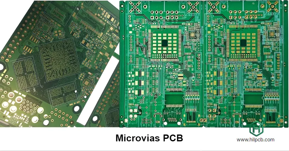
2. Microvias Drilling and Plating Fill: Interlayer connections rely on laser-drilled microvias. The diameter of these vias is typically 20-30 microns. Ensuring the drilling quality of each microvia, hole-wall cleanliness, and the uniformity of subsequent plating fill is critical for guaranteeing the long-term reliability of interlayer connections. The failure of just one microvia could lead to the breakdown of an entire HBM channel.
3. Lamination and Registration Accuracy: Manufacturing a multi-layer interposer requires precisely aligning and pressing each layer together. Interlayer registration errors must be controlled within a few microns, otherwise, vias and pads won't align, causing opens or shorts. This demands top-tier alignment systems and strict environmental controls (temperature, humidity, cleanliness).
4. Warpage Control: As mentioned earlier, warpage is the core challenge in interposer manufacturing. Experienced manufacturers like HILPCB minimize the warpage of the finished board through optimized stackup structures (e.g., using symmetric designs), selecting low-CTE (Coefficient of Thermal Expansion) core materials, and executing precise lamination parameter control, ensuring high yields in downstream packaging stages like CoWoS.
How do you balance performance, cost, and quick-turn delivery cycles?
In the fiercely competitive AI market, Time-to-Market is critical. This creates a demand for HBM3 interposer PCB quick turn services. However, the complexity of interposers seems counterintuitive to the concept of "quick."
Balancing performance, cost, and cycle time is a systemic engineering effort:
- Performance First: For top-tier AI accelerators, performance is non-negotiable. This means the most advanced materials and processes must be used, inherently increasing cost and cycle times.
- Cost Optimization: For more cost-sensitive applications, one can discuss with the manufacturer using slightly lower-performing but highly cost-effective materials, or simplify the design to reduce layer count and process complexity.
- Fast Delivery: The key to achieving HBM3 interposer PCB quick turn lies in the manufacturer's engineering capabilities and process management. A robust DFM (Design for Manufacturability) team engaging early in the design phase can help clients dodge manufacturing pitfalls and cut down on design iterations. Concurrently, mature process flows, stable supply chains, and efficient production scheduling are guarantees for shortened cycles.
As a manufacturer providing one-stop services from prototype to mass production, HilPCB PCB Factory (HILPCB) thoroughly understands this. Through close early-stage technical collaboration with clients and flexible production line configurations, we can deliver highly competitive small batch assembly and rapid prototyping services while guaranteeing top-tier quality.
HILPCB IC Substrate and Interposer Manufacturing Capabilities Overview
| Parameter | Capability Range | Parameter | Capability Range |
|---|---|---|---|
| Max Layer Count | 32+ Layers | Board Thickness Range | 0.1 - 2.0 mm |
| Min Line Width/Space | 8µm / 8µm (SAP) | Min Laser Via Diameter | 25µm |
| Impedance Tolerance | ±5% | Interlayer Registration Accuracy | ±15µm |
| Supported Materials | ABF, BT, High-Speed Laminates | Surface Finish | ENEPIG, OSP |
Your HBM3 Interposer PCB Quality Control Checklist
To systematically guarantee project success, we highly recommend engineers use a detailed HBM3 interposer PCB checklist across various project stages. This checklist is not only a design guide but an effective communication tool with your manufacturer.
Design Stage Checklist:
- Material Selection: Have appropriate low-loss materials (like ABF) been chosen based on SI and thermal performance requirements?
- Stackup Design: Is the stackup symmetric to control warpage? Are power/ground planes sufficient and rationally laid out?
- SI Simulation: Have impedance, crosstalk, and loss simulations been validated for all HBM3 channels?
- PI Simulation: Has the PDN been simulated to ensure impedance meets requirements at target frequencies?
- Thermal Simulation: Has thermal simulation been conducted to identify potential hotspots and verify the effectiveness of the thermal via design?
DFM Stage Checklist:
- Traces and Spacing: Are the designed minimum line width/spacing within the manufacturer's capabilities, leaving sufficient margin?
- Via Design: Is the aspect ratio of microvias reasonable? Does the Via-in-Pad design adhere to manufacturing specifications?
- Tolerance Analysis: Have the impacts of manufacturing tolerances on impedance and timing been considered?
- Warpage Analysis: Has a warpage simulation been conducted with the manufacturer, optimizing the stackup and panelization design?
Manufacturing & QA Stage Checklist:
- Trace Inspection: Is Automated Optical Inspection (AOI) used to inspect every trace layer 100%?
- Interlayer Registration: Is X-ray equipment used to check the registration accuracy of critical layers?
- Impedance Testing: Are test coupons checked for impedance via Time-Domain Reflectometer (TDR) sampling or full inspection?
- Reliability Testing: Have necessary reliability tests, such as thermal cycling and Highly Accelerated Stress Testing (HAST) according to JEDEC standards, been performed?
Common Questions
Why is warpage control so critical for a HBM3 interposer PCB?
Warpage directly affects coplanarity, TIM thickness uniformity, and alignment accuracy between the interposer, HBM stacks, and package substrate. Even small deformation can create hotspots, increase interconnect stress, and reduce downstream packaging yield.
What enables low-loss signal transmission on a HBM3 interposer?
Low-loss transmission depends on stable low-Df materials such as ABF-class dielectrics, fine-line SAP or mSAP fabrication, tight impedance control, and careful optimization of vias, pads, and spacing. At HBM3 data rates, small geometric deviations can quickly become SI problems.
How is power integrity maintained in a HBM3 interposer design?
The design needs an ultra-low-impedance PDN built from well-planned power and ground planes, short current-return paths, and minimized parasitic inductance. Decoupling placement and full-link PI simulation are also necessary to control voltage droop and simultaneous switching noise.
What should engineers verify before releasing a HBM3 interposer PCB to manufacturing?
They should confirm line and spacing margins, microvia and via-in-pad manufacturability, tolerance and warpage analysis, and the planned inspection flow for AOI, X-ray, TDR, and reliability testing. The article's checklist is meant to align design assumptions with real factory capability before build release.
Conclusion
Mastering the future of AI chips begins with a relentless pursuit of perfection in foundational components. HBM3 interposer PCB quality is far from a simple manufacturing metric; it is an artifact synthesizing materials science, high-speed electronics, thermodynamics, and precision manufacturing. From micron-scale signal channels to macro system stability, every detail of the interposer directly influences the ultimate performance and reliability of the AI chip.
To successfully construct high-performance AI interconnect solutions, design engineers must join forces with partners equipped with profound technical heritage and advanced manufacturing capabilities. Using years of experience in the IC substrate and High-Density Interconnect domains, HILPCB provides one-stop services encompassing design optimization, material selection, precision manufacturing, and assembly. We are committed to helping clients tackle the most rigorous challenges, ensuring your HBM3 interposer PCB achieves the highest standards of quality.
Contact HILPCB today to kickstart your high-performance AI chip interconnect project and receive a free DFM evaluation. Together, let's build a rock-solid hardware foundation for the future of artificial intelligence.