
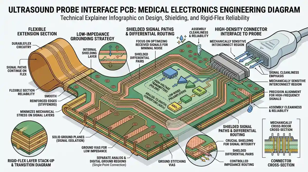
What to Control First During Ultrasound Probe Interface PCB Mass Production
When moving an ultrasound probe interface PCB into mass production, the primary concern isn't simply "whether the signals conduct." The absolute priorities are the physical isolation of the low-noise front-end, the dynamic bending fatigue life of rigid-flex interconnects, post-assembly cleanliness, leakage current risks, and the rigorous process traceability required for medical products. For this class of board, passing tests in a lab is not synonymous with long-term mass production stability, because micro-volt analog signals, dynamic structural bending, high-impedance node contamination, shielding continuity, and batch traceability must all converge perfectly.
Validation Directory
- Quick Overview: Ultrasound Probe Interface PCB Mass Production Review
- The 4 Most Vulnerable Boundaries for Probe Boards
- Risks and Freeze Checklist
- Why Low-Noise Zoning Must Precede Standard Routing
- Why Rigid-Flex Interconnects Are Often the Lifecycle Bottleneck
- Why Cleanliness and Assembly Residues Steal Signal Margin
- Why Shielding, Coplanarity, and Ground Continuity Rewrite Outcomes
- Why Medical Traceability and Validation Loops Must Be Defined Upfront
- Frequently Asked Questions (FAQ)
- Next Steps: Initiating a Probe Interface Board Pre-Review
Quick Overview: Ultrasound Probe Interface PCB Mass Production Review
| Core Dimension | What Happens If Uncontrolled Early On | What to Confirm Before Design Freeze |
|---|---|---|
| Low-Noise Zoning | Elevated noise floor, severe crosstalk, degraded channel consistency. | Physical boundaries for AFE, clocks, power, and digital interfaces. |
| Rigid-Flex Interconnects | Bending zone fractures, connector root fatigue, high RMA rates. | Bending zone definitions, stiffeners, connector mechanical stress paths. |
| Cleanliness | Leakage on high-impedance nodes, signal drift, erratic anomalies. | Cleaning protocols, acceptance criteria, residue risk nodes. |
| Shielding & Assembly | Shielding failure, unstable grounding, poor assembly consistency. | Shielding chassis structure, coplanarity, solder joints, and ground continuity. |
The 4 Most Vulnerable Boundaries for Probe Boards
Risks and Freeze Checklist
| Most Vulnerable Stage | Common Consequences | What to Confirm Before Design Freeze |
|---|---|---|
| Low-Noise Front-End Zoning | Channel crosstalk, high noise floor, degraded repeatability. | Physical isolation and return continuity among AFE, clocks, power, and digital zones. |
| Rigid-Flex Bending Zones | Copper cracking, coverlay damage, connector root fatigue. | Bending area constraints, stiffeners, minimum bend radius, and stress distribution paths. |
| Cleaning & Residue | Leakage currents, baseline drift, erratic faults in humid environments. | Cleaning processes, acceptance criteria, and specific protection for high-Z nodes. |
| Shielding & Assembly | Shielding failure, discountinuous ground, coplanarity issues. | Shielding solder points, ground structures, connector mounting, and flatness criteria. |
| Traceability & Validation | Unresolvable field failures, untraceable batch anomalies. | Material batches, process parameters, test logs, and rigid version control protocols. |
Why Low-Noise Zoning Must Precede Standard Routing
The most critical mistake when designing an ultrasound probe interface board is treating its analog front-end (AFE) like a normal digital PCB. It is not merely a matter of "the analog signals are smaller"; the front-end signal chain is hypersensitive to return paths, shielding boundaries, and adjacent noise sources. If clear boundaries separating the AFE, clocks, switching power supplies, and digital interfaces are not established at the floorplanning stage, attempting to patch grounding, shielding, or filtering later is rarely effective. In the context of medical devices, the public safety frameworks represented by IEC 60601-1 mandate that the boundaries of sensitive front-ends cannot be handled with consumer-electronics-grade leniency.
Priorities to confirm early:
- Does an unbroken, continuous reference plane reside directly beneath the sensitive front-end?
- Are clocks and high-speed digital conduits physically quarantined away from the analog quiet zone?
- Do connectors and cable egress points introduce parasitic coupling paths?
- Is the analog return path severed by digital grounds, power planes, or structural isolation slots?
- Do long, sensitive unshielded routing segments span from the probe head to the interface area?
If the noise boundaries of these boards are vague from day one, engineers will invariably spend weeks retrofitting prototype boards with copper tape to salvage them.
Why Rigid-Flex Interconnects Are Often the Lifecycle Bottleneck
Rigid-Flex interconnects are frequently the bottleneck for system longevity because the flexible portion is not just a prolonged wire—it is a structural component enduring both electrical connectivity duties and repetitive mechanical displacement. If the probe interface board must bend, twist, and absorb repeated plug-in forces within a cramped housing, any ambiguity in defining the bend zones, stiffener placements, and connector stress paths will exponentially magnify fatigue during mass production. According to the public design framework in IPC-2223D, bending zones, structural transitions, and stress routing should never be treated as standard layout regions.
Robust engineering practices typically include:
- Explicitly delineating dynamic flex zones versus static flex zones in the fabrication drawings.
- Banning vias, sharp routing angles, and sudden rigid transitions within the sensitive bending zones.
- Deploying appropriate localized stiffeners under connectors, dense pad arrays, and stress roots.
- Factoring in the pulling and twisting paths introduced by assembly and maintenance maneuvers during design reviews.
- Forcing the mechanical, cable, and PCB layout teams to jointly sign off on the bending boundaries.
Many rigid-flex failures are not electrical design flaws, but occur because real-world mechanical operating conditions were never integrated into the PCB design freeze criteria.
Why Cleanliness and Assembly Residues Steal Signal Margin
Cleanliness and assembly residues actively steal signal margin because ultrasound probe interface boards contain exceptionally high-impedance nodes, micro-volt signal paths, and front-ends sensitive to humidity. In these critical areas, flux residue, incomplete cleaning cycles, or localized contamination are not mere cosmetic defects; they metamorphose directly into treacherous leakage paths, DC bias drift, and sporadic functional anomalies. Viewed through the soldering and assembly context of IPC J-STD-001, cleanliness and assembly consistency are definitive process control imperatives, not subjective guidelines to be debated after field failures arise.
During mass production introduction, intense focus must be placed on:
- Identifying precisely which nodes are most vulnerable to surface leakage.
- Verifying whether the cleaning process effectively penetrates under localized RF shields, connector roots, and densely packed fine-pitch components.
- Ensuring acceptance criteria rely on controlled cleanliness validation methodologies (e.g., ROSE testing or Ion Chromatography) rather than just visual inspections.
- Deciding whether high-impedance paths or exposed solder joints require supplementary protective conformal coatings.
- Guaranteeing that washing, baking, and vacuum packaging are mandated under a singular controlled document.
For medical electronics, this discipline cannot be handled via verbal agreements; it must be crystallized into explicit process requirements and logged acceptance records.
Why Shielding, Coplanarity, and Ground Continuity Rewrite Outcomes
Shielding, coplanarity, and ground continuity heavily dictate final outcomes because many ultrasound interface boards behave perfectly on the bench as bare assemblies, but degrade rapidly once integrated into the probe housing. It is only during system assembly that the cumulative effects of shielding cases, mated connectors, the outer chassis, and localized compressive forces materialize. If ground continuity is erratic or if coplanarity tolerances are exceeded, both the noise floor and channel consistency will degrade simultaneously.
Before design freeze, concurrently confirm:
- Do shield-can solder joints and grounding spring-fingers possess stable, low-impedance return paths?
- Is the assembly flatness (coplanarity) between the connectors and the board surface strictly controlled?
- Will large components, metallic brackets, or structural supports apply warping pressure to the board surface?
- Do the grounding solder joints satisfy both electrical conductivity and mechanical assembly reliability?
- Is post-assembly ground continuity explicitly scheduled into the final test matrix?
For these projects, shielding is not simply "adding a metal can"—it is an integrated structural component of the entire board-level grounding architecture.
Why Medical Traceability and Validation Loops Must Be Defined Upfront
Medical traceability and closed validation loops must be instituted upfront because an ultrasound probe interface board is not a disposable consumer gadget. The moment a product enters the medical device ecosystem, material batches, process parameters, assembly logs, and validation yields must be explicitly traceable back to locked revision files. If this chain is broken, diagnosing whether a subsequent failure stems from a design flaw, a material anomaly, an assembly deviation, or field abuse becomes impossible. From the perspective of regulatory oversight and quality systems outlined in ISO 13485 and FDA Ultrasound Guidance, traceability is not an optional premium feature; it is the foundational prerequisite for any medical interface board to enter validation and clearance workflows.
Practical pre-release checklists usually encompass:
- Material & Revision Traceability: Are batches of base laminates, coverlays, stiffeners, connectors, and key silicon components rigorously traceable?
- Process Traceability: Are cleaning cycles, baking times, assembly profiles, shield soldering metrics, and critical process parameters archived securely?
- Mechanical Traceability: Are bend radii limits, assembly torque/pressure, and connector retention methods locked within controlled documentation?
- Electrical Validation: Has a baseline been established for noise floors, channel consistency, leakage vulnerabilities, and post-assembly functionality?
- Reliability Validation: Is there a targeted matrix testing limits for bending fatigue, temperature/humidity cycling, and post-assembly electrical re-tests?
- Closed-Loop Anomaly Resolution: If sporadic defects occur, can the system rapidly trace them back to specific batches, processes, and design revisions?
The earlier this closed-loop system is deployed, the less likely the team will face the agonizing "we know there's a problem, but lack the evidence to pinpoint it" scenario during pilot runs and certification phases.
Frequently Asked Questions (FAQ)
Q: Why does the noise performance look perfect in the lab, but degrades instantly during pilot production?
A: Because pilot production introduces real-world assembly forces, shielding enclosures, mated connectors, varied cleaning yields, and mechanical stresses. These physical realities collectively alter the front-end noise boundaries that static lab tests ignore.
Q: Is the analog front-end the only critical part of an ultrasound probe interface board?
A: No. While the low-noise front-end is vital, the rigid-flex structural integrity, absolute cleanliness, shielding continuity, and rigorous traceability framework equally govern mass production stability.
Q: Why do rigid-flex boards expose so many problems during pilot runs?
A: Because pilot runs introduce real assembly manipulation, insertion forces, actual bending paths, and batch variations. Mechanical fatigue and structural weaknesses typically only reveal themselves during this phase.
Q: Why is cleanliness so uniquely critical for this type of board?
A: Because high-impedance nodes and micro-volt analog pathways are overwhelmingly susceptible to surface residues and parasitic leakage paths. For these boards, cleaning validation must be chemically controlled, not merely assessed visually.
Q: What constraints are most important to freeze before signing off on a medical interface board layout?
A: Prioritize freezing the low-noise isolation partitioning, rigid-flex bend boundaries, specific cleaning mandates, shielding and grounding architecture, traceability protocols, and the final validation matrix.
Next Steps: Initiating a Probe Interface Board Pre-Review
If your engineering team is developing ultrasound probe interface boards, medical front-end acquisition modules, or any low-noise medical PCB involving rigid-flex interconnects, the most effective proactive measure is not asking "can this board be fabricated?", but compiling the following data for an advance pre-review:
- Specific zoning maps separating AFE, clocks, power, and digital interfaces.
- Rigid-flex bending definitions, stiffener locations, and connector mechanical stress paths.
- Mandatory requirements for cleaning, packaging, and high-impedance node protection.
- Validation protocols for post-assembly noise metrics, shielding effectiveness, and traceability tracking.
If you wish to conduct a comprehensive ultrasound interface PCB design audit, a Rigid-Flex reliability assessment, or a medical mass-production DFM review prior to pilot runs, you can directly contact the PCB Engineering Team to discuss the specifics of your program.
Further Reading:
- Flex and Rigid-Flex PCB Capabilities
- SMT Assembly Capabilities
- PCB Manufacturing and Engineering Support
- Design Handoff Best Practices
- Reliability Test Matrix
*Author: HILPCB Engineering Content Team* *Reviewed by: HILPCB Medical / DFM Engineering Team* *Last Updated: 2026-04-13*