
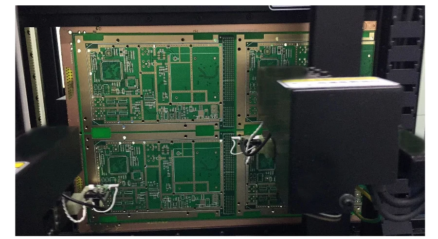
A weather radar PCB is one of several RF, power, control, processing, interface, or display assemblies used inside an airborne weather radar system. The board supports the radar's intended function, but it does not detect hazardous weather, achieve airworthiness approval, or satisfy a system performance standard by itself.
This guide translates radar requirements into PCB construction, evidence, and supplier boundaries without assuming one solution fits every installation.
Key Takeaways
- Allocate each board's role before choosing laminate, stackup, copper, cooling, shielding, or test limits.
- Build RF requirements as a loss, impedance, phase, noise, isolation, and thermal budget with conditions—not as a generic “X-band PCB” label.
- Separate high-energy transmit paths from sensitive receive paths physically and electrically; the main RF power may travel through modules, connectors, waveguide, or other structures outside the PCB.
- RTCA DO-220 series requirements concern airborne radar system functions. PCB fabrication evidence supports, but does not replace, radar-system testing.
- DO-254 objectives and assurance levels come from the approved system/certification process; a PCB supplier cannot assign a DAL from the board name.
- DO-160 environmental categories follow the equipment installation and certification basis. Do not quote a universal temperature, vibration, lightning, or humidity profile.
- Freeze stackup, material equivalence, copper profile, surface finish, RF launch, coupon, test method, and change authority in the purchase package.
Table of Contents
- How airborne weather radar works
- Map radar functions to PCB responsibilities
- Create an RF performance budget
- Select the stackup and materials
- Control transmit receive and digital coupling
- Design power integrity and thermal paths
- Connect DO-254 and DO-160 to board evidence
- Build an environmental evidence matrix
- Manage reliability configuration and supply chain
- Validate from coupon to airborne equipment
- Common failures and first evidence
- Weather radar PCB RFQ checklist
- Reference standards and responsibility boundaries
- How HILPCB can support the PCB package
- Frequently asked questions
How Airborne Weather Radar Works
Airborne weather radar transmits RF energy, receives echoes from hydrometeors, and processes the returned signals to present supported weather or hazard information. Signal strength and phase/frequency behavior can support different functions, but not every radar implements every function. RTCA DO-220 series documents treat weather detection, ground mapping, forward-looking windshear, turbulence, atmospheric-threat, and high-altitude ice-crystal functions as distinct capabilities that may be implemented individually or in combination.
Radar has physical limits. Heavy-precipitation attenuation can hide activity; clutter and antenna tilt affect the display; weak reflectivity does not exclude every hazard. These limits affect dynamic range, protection, calibration, processing and verification.
Many airborne weather radars use X-band, but band, waveform, power, antenna, functions, and certification basis come from the system specification—not automotive-radar rules.
Map Radar Functions to PCB Responsibilities
Start with an interface control document (ICD); one radar may contain several boards with different risks and manufacturing needs.
| Board or module role | Typical functions | PCB-critical risks | Major interfaces outside the board |
|---|---|---|---|
| Transmitter/exciter control | Timing, bias, modulation, monitoring, protection | Pulse/current return, timing jitter, isolation, device protection and heat | RF power device, waveguide/coax, antenna, power conversion and cooling |
| Receiver/front end | LNA/mixer/IF, gain control, filtering, receiver protection | Noise figure contribution, insertion loss, leakage, shielding and compression/recovery | Antenna/duplexer, calibrated sources and RF enclosure |
| Frequency synthesis/timing | LO generation, clocks, synchronization | Phase noise, spurs, reference integrity and crosstalk | Reference oscillator, RF front end and processors |
| Digital processing | ADC/DAC, FPGA/processor, memory and high-speed links | PDN noise, clock/data integrity, thermal load and configuration control | Software, programmable logic data, displays and aircraft buses |
| Power/interface | Input protection, conversion, discretes and communications | Conducted susceptibility/emissions, transients, grounding and fault containment | Aircraft power, bonding, wiring and LRU enclosure |
| Antenna/scanner control | Position sensing, motor/actuator control or array control | Power noise, feedback accuracy, connector stress and fault detection | Antenna mechanics/array, position sensors and drive electronics |
Keep this table program-specific. A solid-state array, mechanically scanned antenna, magnetron-based transmitter, and integrated radar sensor impose different boundaries.
Create an RF Performance Budget
“Controlled impedance” is only one line in an RF budget. Translate system performance into measurable board-level allocations.
| Budget item | Inputs to define | Manufacturing evidence |
|---|---|---|
| Impedance/return loss | Line type, target/tolerance, frequency, reference plane, launch and connector model | Approved stackup, field-solver geometry, impedance coupon and test method |
| Insertion loss | Frequency band, path length, temperature, finish, connector/launch de-embedding and margin | Material lot data as required, conductor profile, coupon or representative path measurement |
| Phase/length match | Channel relationship, electrical delay, reference point and temperature | Artwork/stackup control plus differential/phase coupon when justified |
| Receiver noise contribution | Pre-LNA loss, leakage, grounding, bias noise and shielding | Layout review, material/finish control and module-level noise verification |
| Isolation | TX-to-RX, LO-to-RF/IF, digital-to-analog, power-to-RF and antenna-channel coupling | Stackup/layout evidence, shielding/bonding details and S-parameter/system tests |
| Power handling | CW/pulsed waveform, duty cycle, mismatch, altitude/pressure and fault state | Copper/thermal construction, spacing, RF launch validation and stress test |
| Stability/calibration | Temperature, aging, moisture, supply variation and calibration interval | Material/process traceability plus environmental and calibration results |
Use self-contained limits: “50 ohm” without layer, tolerance, frequency and reference geometry is incomplete. A data-sheet dielectric constant is not automatically the design value for the chosen construction.
Select the Stackup and Materials
Choose the stackup from performance and environment, then obtain a manufacturable proposal before layout freeze. Relevant properties include dielectric constant and its tolerance, dissipation factor, copper roughness, glass style/resin content, moisture absorption, thermal conductivity, glass-transition behavior, decomposition temperature, Z-axis expansion, peel strength, bondply availability, thickness tolerance, finish compatibility, and lot/documentation needs.
Not every radar board needs homogeneous PTFE or a named laminate. Hybrid constructions can improve cost/density but add lamination, registration, expansion, drilling, CAF, thickness, and rework risks. Confirm qualified constructions and substitution triggers.
Define:
- layer order, finished thickness/tolerance and copper weights;
- controlled lines, reference planes, cavity/back-drill or via structures;
- RF-launch geometry, connector footprint and mechanical datum;
- conductor treatment/roughness assumptions used in the model;
- resin system, glass style or performance envelope and substitution rules;
- surface finish by function, including RF loss, bonding, soldering and storage needs;
- impedance/loss coupons, test frequencies, methods, sample plan and report format.
Control Transmit Receive and Digital Coupling
Receiver isolation spans the antenna/duplexer, enclosure, cables, stackup, grounding, power, timing, and control.
On the PCB, partition the signal chain by energy and sensitivity. Keep transmit-switching currents and fast digital returns away from LNA, LO and analog references. Use continuous, intentional return paths; avoid routing across plane splits; control via transitions and stubs; fence only where the electromagnetic model supports it; and coordinate shielding-can lands, seams and grounding with the enclosure.
High-speed ADC/FPGA interfaces add simultaneous-switching noise, reference noise and heat. Treat clock phase noise, converter aperture jitter, power-supply noise and digital crosstalk as one signal-chain budget. A quiet schematic component can still be noisy after an uncontrolled PDN, shared return, connector or enclosure is added.
Design Power Integrity and Thermal Paths
Separate aircraft input-power compliance from internal rail quality. Define normal, abnormal, startup, hold-up, brownout, surge/transient, reverse, fault, and shutdown states. PCB protection must coordinate with wiring, source impedance, bonding, enclosure, filters and downstream loads.
For each heat source, document loss versus mode, duty cycle, ambient/altitude, airflow or cold-plate condition, junction/case limits, interface resistance and allowable gradient. Thermal vias and heavy copper help only when connected to a complete heat path. High RF energy may belong in a module, flange, substrate, coax or waveguide rather than ordinary PCB traces.
Validate credible worst-case modes and correlate thermal models with instrumented hardware; a room-temperature image is not proof.
Connect DO-254 and DO-160 to Board Evidence
RTCA DO-254 describes hardware design life-cycle processes for airborne electronic hardware, including circuit board assemblies and programmable devices. The applicable objectives, independence, data and assurance level arise from the approved aircraft/system development and safety process. The PCB fabricator executes controlled manufacturing requirements; it does not independently declare that a bare board is “DAL B certified.” For how DO-254 and DO-160 fit with other aerospace programs, see our overview of aerospace and defense PCBs.
DO-254-related board data may include traceable requirements, design standards, reviews, implementation data, verification results, problem reports, configuration indexes, change records and conformity evidence. Which items are required depends on the certification plan and hardware classification.
RTCA DO-160 supplies environmental conditions and test procedures for airborne equipment. Test categories are selected from installation and intended environment. Qualifying a coupon or PCB material does not qualify a line-replaceable unit (LRU); the enclosure, connectors, wiring, cooling, software/configuration and installation affect results.
Build an Environmental Evidence Matrix
Do not copy a generic “-55°C to +125°C, MIL-STD-810” table into an RFQ. Map the program's selected categories to failure mechanisms and evidence.
| Environment or test family | PCB/PCBA risks to analyze | Evidence before equipment test |
|---|---|---|
| Temperature/altitude/variation | Material expansion, solder fatigue, RF drift, cooling loss, corona/pressure effects | Material stackup, derating, thermal model, instrumented prototype and workmanship controls |
| Vibration/shock/crash safety | Connector/fixed-mass stress, BGA/LGA joints, board modes, fasteners and fretting | Mechanical model, support/keep-outs, assembly inspection and resonance survey as planned |
| Humidity/fluids/salt or contamination | Leakage, corrosion, finish/coating compatibility and trapped residues | Cleanliness/coating process, material compatibility, test coupons and inspection criteria |
| Power input/voltage spike/audio-frequency susceptibility | Protection stress, filter resonance, resets, rail modulation and RF spurs | Schematic/PDN analysis, component stress, conducted bench tests and event logging |
| RF susceptibility/emissions | Enclosure/PCB coupling, cable common mode, clock harmonics and receiver desense | Stackup/return review, pre-compliance scans and mode-specific operating configuration |
| Lightning-induced transients/ESD | Interface overstress, arcing, latent damage and reset behavior | Protection coordination, spacing, bonding/interface design and controlled injection tests |
MIL-STD-810 may be relevant to a defense contract only when invoked with selected methods, procedures and tailored severities. It is not an automatic “stricter upgrade” to civil airborne qualification.
Manage Reliability, Configuration, and Supply Chain
Reliability comes from allocated requirements and controlled evidence, not universal redundancy or MTBF targets. Redundancy is a system architecture decision that must address independence, common-cause failures, monitoring, switching and latent faults. Component derating must follow the program's approved rules, actual stress, environment and failure mechanisms—not a single percentage example.
Create a part and process control plan covering approved manufacturers, obsolescence, counterfeit avoidance, moisture sensitivity, storage life, solderability, material shelf life, special processes, qualification status, and change notification. For RF boards, treat laminate construction, copper profile, surface finish, press cycles and RF connector launch as configuration-sensitive.
AS9100 certification can support a supplier quality-management system, but it does not certify a particular radar or prove every process is in scope. Verify the certificate scope, site, special processes and customer approvals. Export controls such as ITAR or EAR apply only when the hardware or technical data is controlled and the parties, locations and access are authorized; classify the program before transferring data.
Validate From Coupon to Airborne Equipment
| Level | Evidence | Question answered |
|---|---|---|
| Material/process | Certificates and incoming/lot controls as required | Was the approved construction/process used? |
| Fabrication coupon | Impedance, loss, plating, microsection and selected reliability tests | Did the manufactured stackup meet defined PCB characteristics? |
| Bare board | AOI, electrical test, dimensional/visual acceptance and traceability | Does the PCB match released data and acceptance criteria? |
| PCBA | SPI/AOI/X-ray, workmanship, programming and electrical/functional screens | Was the assembly built correctly and does it pass board-level limits? |
| RF module | S-parameters, gain/noise/phase/spur/power/calibration and thermal tests | Does the integrated RF chain meet its allocated budget? |
| Equipment/LRU | Radar functions, built-in test, interfaces and selected DO-160 categories | Does the equipment perform in its declared configuration/environment? |
| Aircraft/system | Installation, safety, interference and operational/certification tests | Does the installed radar meet intended function and certification basis? |
Preserve test configuration, calibration, firmware/programmable-logic loads, cables, fixtures, limits, raw data and deviations. A passing PDF without configuration identity is weak evidence.
Common Failures and First Evidence
| Symptom | Plausible cause | First useful evidence |
|---|---|---|
| Excess insertion loss | Material/roughness variation, finish, geometry, launch, connector or de-embedding error | Coupon/line S-parameters, stackup microsection and calibration method |
| Receiver desense during transmit/digital activity | Leakage, shared return/rail, shielding seam, LO spur or timing | Synchronized RF, rail, current and control-state measurements |
| False or degraded weather presentation | Calibration, antenna/tilt, attenuation handling, receiver chain or processing/configuration | System test mode, calibrated target/stimulus and configuration log |
| Thermal drift or shutdown | Incorrect loss/duty model, interface resistance, airflow or sensor placement | Mode-specific power and instrumented thermal map |
| DO-160 failure after board tests pass | Enclosure, cable, power, bonding, installation or category not represented at board level | Equipment setup, category, operating mode and coupling path |
| Intermittent vibration fault | Connector/fretting, board resonance, heavy component, solder joint or fastener | Event-synchronized continuity, accelerometer data, X-ray and teardown |
| Repeat build changes RF result | Uncontrolled material, copper profile, press, finish, CAM or supplier change | Configuration index, lot genealogy, coupon correlation and change history |
Weather Radar PCB RFQ Checklist
System allocation and environment
- board role, radar functions, waveform/frequency information authorized for release and interface control document;
- safety/assurance allocation, certification plan responsibilities and required lifecycle records;
- selected DO-160 categories or equipment environmental requirements, installation and cooling boundary;
- power modes, fault/transient conditions, RF power/duty, sensitivity, timing and calibration requirements.
PCB and assembly package
- controlled Gerber X2/ODB++/IPC-2581, netlist, stackup, fabrication and assembly drawings;
- impedance/loss/phase table with frequency, reference planes, tolerances and de-embedding;
- RF material/construction, copper profile, surface finish and allowed-equivalent rules;
- via/back-drill/cavity/edge-launch, shielding, bonding, connector and thermal-interface details;
- BOM/AVL, component derating/control, firmware/programming data and special-process specifications.
Supplier evidence and change control
- proposed stackup/materials, field-solver results and manufacturability exceptions;
- coupon design, test method/frequency, sample plan, calibration and raw/report data;
- first-article, microsection, electrical, assembly inspection and functional/RF test scope;
- lot/unit traceability, storage/handling, nonconformance, repair and record retention;
- substitutions, CAM changes, process/site transfers, obsolescence and requalification triggers;
- security/export-control handling, authorized access and return/destruction of controlled data when applicable.
Reference Standards and Responsibility Boundaries
Applicable references may include:
- RTCA DO-220 series, Minimum Operational Performance Standards for airborne radar functions
- RTCA DO-160 series, environmental conditions and test procedures for airborne equipment
- RTCA DO-254, design assurance guidance for airborne electronic hardware
- SAE ARP4754 series, development of civil aircraft and systems
- SAE ARP4761 series, safety assessment processes for civil airborne systems and equipment
- RTCA DO-178C when airborne software is in scope
- AS9100, aerospace quality-management systems where contractually applicable
- IPC-2221, IPC-2222 and IPC-6012 for PCB design and performance requirements as invoked
- IPC-6018 for high-frequency/microwave printed boards when invoked
- IPC-A-600, J-STD-001 and IPC-A-610 for acceptability/workmanship as invoked
Use the exact program-approved revisions and clauses. The applicant/legal equipment owner controls intended function, safety allocation, certification basis, radar performance, software/programmable logic, environmental categories and aircraft integration. The PCB/PCBA supplier owns only the contracted construction, processes, tests, records and disclosed changes.
How HILPCB Can Support the PCB Package
HILPCB can review manufacturability for high-frequency PCB and dense HDI PCB constructions, subject to the exact materials, stackup, RF features, tolerances, documentation and test scope accepted in the quotation. This support does not constitute radar-system or airworthiness approval.
Send the ICD excerpt authorized for manufacturing, controlled artwork, stackup, RF budget, coupon and test requirements, assembly data, traceability plan, selected acceptance criteria, and change-control rules. Ask HILPCB to return assumptions, exceptions, proposed construction, evidence limits and any unavailable qualification or security requirement through the quote page.
Frequently Asked Questions
Is a weather radar PCB always an X-band RF board?
Many airborne weather radars use X-band, but the system specification controls frequency, waveform and board role. Power, control, processing and interface boards may have very different RF requirements or no routed microwave path.
Does DO-254 certify a PCB?
DO-254 provides design-assurance guidance for airborne electronic hardware lifecycles. Compliance evidence belongs to the approved hardware/certification process; a bare PCB fabricator cannot independently assign or certify a design assurance level.
Can a PCB pass DO-160 testing by itself?
A board may undergo development or screening tests, but DO-160 categories normally qualify airborne equipment in a defined configuration. Enclosure, connectors, wiring, cooling, software state and installation interfaces affect the result.
Must every aerospace radar PCB use MIL-STD-810 and ITAR controls?
No. MIL-STD-810 applies only when a contract invokes tailored methods and severities. ITAR/EAR controls depend on classification, parties, data and destination; they are not automatic for every aerospace PCB.
What data should accompany an RF weather radar PCB quote?
Provide controlled manufacturing files, stackup, material rules, frequency-dependent impedance/loss/phase limits, RF launches, thermal boundary, environmental allocation, coupons, test methods, traceability and change-control requirements.
Conclusion
A reliable weather radar PCB begins with a precise system allocation. Convert radar performance and environmental requirements into board budgets, freeze the construction and evidence plan, control every change, then verify progressively from coupon to installed equipment. This preserves the essential distinction between manufacturing a capable board and approving an airborne radar system.