
Design and engineering
Freeze stackup, materials, finished dimensions, copper, hole structures, impedance targets, and the failure modes the build must control.
HILPCB QUALITY EVIDENCE
A board is ready for release when its requirements, process controls, inspection methods, and records answer the project's actual risks. This guide shows what engineers, NPI teams, and buyers should request and verify.
Last updated: 2026-08-23
DECISION FIRST
It should connect a released requirement to a defined process or inspection method, a recorded result, and an owner for any exception. A certificate alone is not a finished-board qualification, and an inspection acronym alone is not acceptance evidence.
Freeze stackup, materials, finished dimensions, copper, hole structures, impedance targets, and the failure modes the build must control.
Define process windows, inspection coverage, sample plans, reaction rules, traceability depth, and the records that move into the next gate.
Normalize the RFQ so suppliers quote the same construction, acceptance limits, evidence set, retention period, and change-notification boundary.
EVIDENCE MAP
| Project question | Useful evidence | Boundary to state |
|---|---|---|
| Are visible features and workmanship within the drawing? | Visual inspection, AOI, dimensional records | Coverage depends on feature access, class, drawing, and programmed limits. |
| Are hidden joints or internal structures acceptable? | X-ray, microsection, internal-layer review | Sample plan, section location, and acceptance criteria must be specified. |
| Are nets continuous and isolated? | Electrical test confirmation | Test coverage follows net access, tooling, test limits, and released data. |
| Does a controlled structure meet its electrical target? | Impedance coupon/TDR data, or agreed RF measurement | Reference plane, fixture, de-embedding, frequency range, and tolerance matter. |
| Can a board or lot be traced after release? | Material CoC, lot/serial records, traveler, inspection and test linkage | Retention depth and change-notification rules belong in the order scope. |
For assembled boards, PCBA functional testing should follow the released test plan, fixture or interface requirements, operating conditions, limits, and acceptance records.
ICT testing for PCB assembly checks accessible nets and defined electrical limits when the design, test data, and fixture access support the method.
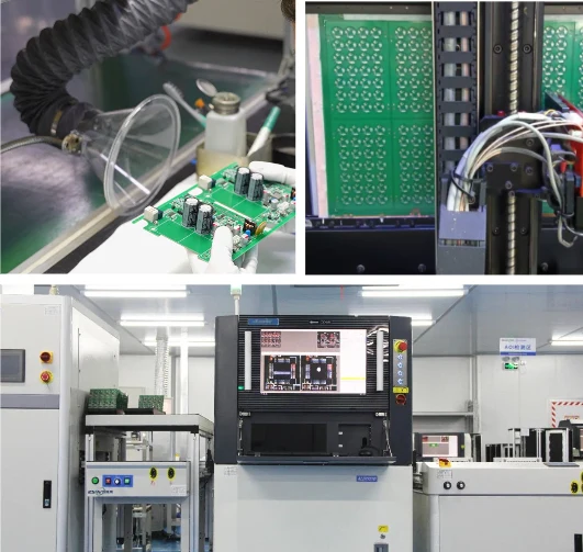
AOI inspection for PCB assembly addresses visible placement and workmanship features, while X-ray inspection for PCB assembly is reserved for agreed hidden-joint or internal-structure risks.
A PCBA testing service should be defined by the product risk and released test plan: ICT, flying probe, functional test, AOI, X-ray, or other methods are selected for the evidence the build actually needs. The applicable evidence set is confirmed against the released design and quotation. No single method proves every product-level requirement.
RELEASE CHECKLIST
FAQ
Request the released drawing and stackup, material identity or CoC when required, dimensional and visual inspection records, electrical test confirmation, microsection or impedance data where the design risk requires it, and lot or serial traceability. The method, sample plan, limits, and included records should be agreed in the quotation.
No. A management-system certificate or material certificate supports a defined manufacturing or material claim. Product qualification remains the responsibility of the project team and depends on the complete board, assembly, environment, validation plan, and applicable regulatory requirements.
Use the method that answers the project risk: AOI for visible placement and workmanship features, X-ray for hidden joints or structures, microsection for internal interconnect evidence, electrical test for continuity or isolation, and impedance or TDR data for controlled structures when specified. These methods are complementary, not interchangeable.