
FR4 PCB Manufacturer | High-Tg, Multilayer & Heavy Copper
FR4 PCB manufacturing for standard, high-Tg, halogen-free and lower-loss constructions. Our manufacturing envelope includes up to 64 layers, up to 20 oz copper and 24-hour expedite for eligible builds, with the material, stackup, geometry and test plan confirmed before release.
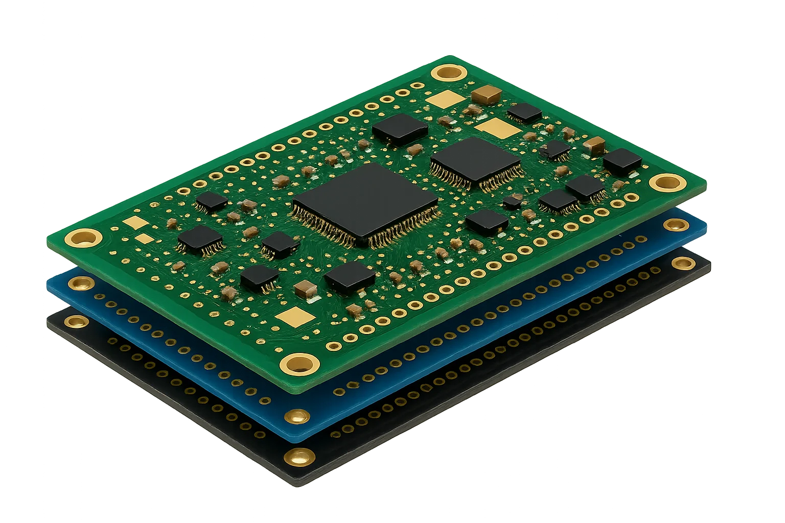
FR4 PCB Material Selection: Tg, Td, Dk, Df and CTI
Specify the laminate by the design risk, not by the FR4 label aloneFR4 is a material family, not one fixed electrical or thermal specification. Standard FR4 is often the cost-effective route for general electronics. High-Tg or thermally robust grades may be appropriate when the stackup, lead-free reflow exposure, copper mass or operating environment creates a tighter thermal margin. Lower-loss FR4 can extend the useful range of conventional processing when the channel loss budget does not justify a dedicated RF laminate.
For each project, HilPCB reviews the required glass-transition temperature (Tg), decomposition temperature (Td), Z-axis expansion, dielectric constant (Dk), dissipation factor (Df), comparative tracking index (CTI), flammability, halogen requirement and approved material list. Datasheet values depend on the material construction and test method; they are not automatic finished-board guarantees. See our FR4 material guide or compare specialized options on the high-frequency PCB manufacturing page.
The quotation should identify the proposed manufacturer and grade, approved substitutes, stackup revision and any material certificate required at shipment. That gives engineering a defined model input and gives procurement a comparable material scope.
- Standard, mid-Tg and high-Tg FR4 review
- Lower-loss, halogen-free, high-CTI and CAF-resistant options
- Supplier Dk and Df checked with their stated test conditions
- Material availability and approved-substitute control
- Copper profile, resin content and glass style reviewed with the stackup
- Material certificate or certificate of conformance when quoted
🚀 Quick Quote Request
📋 Get Full Capabilities
FR4 PCB Manufacturing Review for Multilayer, HDI and Heavy Copper
Layer count, copper, geometry, vias and lead time must be approved as one constructionOur industry-leading manufacturing processes support conventional FR4, multilayer, controlled-impedance, HDI and heavy-copper programs from prototype through production. The manufacturing envelope reaches up to 64 layers, up to 20 oz copper, 2/2 mil trace and space, laser microvias and ±5% controlled impedance. These are advanced review limits and are not automatically combinable.
Feasibility is set by the actual finished thickness, copper distribution, trace and space, drill spans, via aspect ratio, sequential lamination count, panel size, registration margin, resin fill and surface finish. For example, heavy copper changes etch compensation and dielectric-fill requirements, while fine geometry and high layer count reduce the available process margin. HilPCB returns the approved stackup and any DFM questions before order release.
A 24-hour expedite route is available for eligible FR4 builds after material, files, quantity and current capacity are reviewed. More complex multilayer, HDI, special-material or report-heavy orders receive a project-specific schedule rather than a generic quick-turn promise.
- DFM review of Gerber or ODB++, drill, drawing and stackup data
- Copper balance, resin-fill and lamination-cycle review
- Mechanical, blind, buried and laser-via feasibility review
- Impedance table, reference planes and coupon scope checked together
- Prototype construction documented for repeat production
- Expedite eligibility confirmed on the quotation
FR4 PCB Manufacturing Capabilities
Use standard values for initial design screening and advanced values only after combined review
| Decision Area | Standard Route | Advanced Review | Confirmation Basis |
|---|---|---|---|
Layer Count | 1-12 layers on the standard FR4 route | Up to 64 layers | Released stackup and lamination review |
FR4 Materials | Standard, mid-Tg and high-Tg FR4 | Lower-loss, halogen-free, high-CTI, CAF-resistant or customer-specified grades | Approved material list and supplier datasheet |
Finished Thickness | 0.6-3.2 mm design screen | 0.2-10.0 mm by stackup and handling review | Fabrication drawing and pressed stackup |
Finished Copper | 0.5-4 oz design screen | Up to 20 oz copper | Copper distribution, geometry and resin-fill review |
Trace / Space | 4/4 mil design screen | Down to 2/2 mil on eligible constructions | Finished copper, etch compensation and panel review |
Drill & Via Structure | 0.20 mm mechanical drill and plated through holes | Laser microvias, blind/buried vias, via-in-pad and sequential HDI | Drill data, aspect ratio and lamination sequence |
Controlled Impedance | ±10% design screen | ±5% when the stackup, coupon and TDR scope are approved | Impedance table and order-specific acceptance method |
Panel Size | Up to 571.5 × 609.6 mm standard panel screen | Oversize options up to 571.5 × 1200 mm by review | Panel drawing, copper balance and equipment route |
Surface Finish | Lead-free HASL, OSP or ENIG | ENEPIG, immersion silver, hard/soft gold or specified finish | Assembly, storage, contact and bonding requirements |
Inspection & Test | Visual inspection and electrical test plan | AOI, impedance coupon/TDR, microsection or dimensional records when quoted | Purchase specification and quality plan |
Standards & Certification Scope | IPC class and acceptance revision specified by the customer | Regulated-industry and certificate requirements reviewed for the applicable site and order | Quotation, quality agreement and current certificate |
Lead Time | Confirmed after material and fabrication-file review | 24-hour expedite for eligible builds | Approved files, quantity and current production schedule |
Order Deliverables | Approved stackup, material and build requirements recorded with the order | Material CoC, coupon data, microsection or inspection records when quoted | RFQ deliverable list and purchase order |
Need capabilities beyond this product? Explore our full manufacturing capabilities
Ready to start your PCB project?
Whether you need simple prototypes or complex production runs, our advanced manufacturing capabilities ensure excellent quality and reliability. Get your quote within 30 minutes.
FR4 PCB RFQ Requirements for an Actionable Quote
Send the latest Gerber or ODB++ package, NC drill files, fabrication drawing and proposed stackup. State the finished thickness, layer functions, copper weights, minimum geometry, hole and via structure, surface finish, outline tolerance, quantities and required delivery date.
For material-controlled work, include the laminate manufacturer and grade or the required Tg, Td, Dk/Df reference conditions, CTI, flammability and halogen requirements. For controlled impedance, include target values, tolerance, routing layer, reference plane and coupon requirement. Also identify the applicable IPC revision/class, electrical test, inspection sampling, material certificate, microsection, impedance report and traceability expectations.
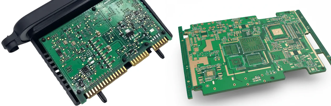
Standard FR4 vs High-Tg, Lower-Loss, High-CTI and Halogen-Free FR4
- Standard FR4: use when cost, general mechanical strength and common assembly exposure drive the decision.
- High-Tg or thermally robust FR4: review for denser multilayers, repeated lead-free reflow, higher copper mass or demanding thermal environments. Tg alone does not define thermal reliability; Td and Z-axis expansion also matter.
- Lower-loss FR4: consider when insertion-loss and timing budgets exceed standard FR4 performance but the design can remain on an FR4-compatible process.
- High-CTI FR4: specify when tracking resistance and insulation coordination are part of the electrical safety design.
- Halogen-free FR4: use when the product environmental specification requires it; confirm the exact declaration and laminate grade rather than assuming all FR4 is equivalent.
FR4 PCB Stackup and Controlled-Impedance Review
Controlled impedance depends on the pressed dielectric thickness, resin content, glass style, copper profile, finished trace geometry, reference plane and solder mask. HilPCB reviews the proposed stackup against the impedance table and identifies any geometry changes needed for the selected laminate construction.
When impedance is an acceptance requirement, define the target and tolerance in the purchase data and state whether a stackup coupon and TDR result are required. A generic Dk value or field-solver screenshot does not replace an approved production stackup and measurement method. Read our controlled-impedance PCB guide for the required design inputs.
FR4 PCB Testing, Material Certificates and Quality Records
Inspection and documentation should match the project risk. The order can define electrical testing, AOI scope, impedance coupon results, microsections, dimensional reports, material certificates, flammability evidence, lot identification and other customer records. These deliverables are included only when stated in the quotation or quality agreement.
For procurement, require the quote to name the proposed material grade, substitution rule, IPC acceptance basis, included test coverage, report format and lead time. For engineering, keep the released stackup, impedance table, drill data and approved deviations with the fabrication package. This makes repeat orders auditable without implying that every FR4 order receives the same evidence bundle.
FR4 PCB Applications and When to Choose Another Material
FR4 PCB manufacturing supports industrial controls, power supplies, automotive electronics, medical equipment, communications hardware, servers, consumer products and general embedded systems. Material and construction choices still depend on voltage, heat, signal loss, dimensional stability, reliability target and assembly exposure.
Choose a dedicated high-frequency PCB material when the RF or insertion-loss budget exceeds an FR4-compatible construction. Review metal-core PCB options when heat spreading dominates, heavy-copper PCB for high-current conductors, and HDI PCB when dense BGA escape or microvias drive the build.
FR4 PCB Prototype-to-Production Change Control
The prototype should establish an approved material, stackup, copper construction, via route, impedance method, surface finish and inspection scope. Repeat production can then reference the same released package instead of relying on a generic FR4 description.
If material availability requires a substitute, or if copper, geometry, stackup, panelization or test scope changes, the effect should be reviewed before release. Written approval keeps procurement savings from becoming an unplanned electrical, thermal or reliability change.
- Prototype: close DFM, material, stackup and acceptance questions
- Pilot: verify the released construction and required records
- Production: control substitutions, deviations and repeat-order revisions
Frequently Asked Questions
What is FR4 PCB material?
What files do you need to quote an FR4 PCB?
When should I choose high-Tg or lower-loss FR4?
Can you combine 64 layers, 20 oz copper, 2/2 mil geometry and ±5% impedance?
Is 24-hour FR4 PCB manufacturing available?
What FR4 PCB quality documents can I request?
Experience Advanced PCB Manufacturing Excellence
From simple prototypes to complex production runs, our world-class factory delivers superior quality, fast turnaround and competitive pricing. Join thousands of satisfied customers who trust us with their PCB manufacturing needs.