
In medical imaging and wearable devices, safety and reliability are non-negotiable. Every design choice and every production operation can directly affect patient safety and the accuracy of diagnostic data. Under this strict reality, Fixture design (ICT/FCT) is no longer “just another test step” on the line. It becomes a lifecycle-critical pillar that helps ensure compliance with core regulations such as IEC 60601 electrical safety and ISO 10993 biocompatibility. A well-engineered fixture turns abstract regulatory language into measurable, repeatable test conditions—building a robust quality and compliance firewall from the start.
For high-density, highly integrated medical PCB, challenges appear at every stage from prototype verification to mass production. Whether it’s a complex SMT assembly process or tight component placement, tiny deviations can lead to catastrophic outcomes. That’s why a scientific Fixture design (ICT/FCT) strategy, paired with thorough DFM/DFT/DFA review, becomes the bridge between design, manufacturing, and regulations. It validates not only basic circuit function, but also simulates extreme electrical and environmental stresses seen in real use—ensuring the device maintains basic safety and essential performance in all conditions. As a specialist in medical electronics, HILPCB understands these constraints deeply and delivers end-to-end solutions—from design and manufacturing to test validation—so customers can navigate complex compliance requirements with confidence.
The core role of Fixture design (ICT/FCT) across medical-device NPI stages
Across NPI stages—EVT, DVT, and PVT—the effectiveness of the test strategy directly determines time-to-market and final quality. In this critical flow, Fixture design (ICT/FCT) connects the stages and provides the foundation for stable progress through NPI EVT/DVT/PVT.
In EVT, the design is still evolving and volumes are low. Flying probe test is often favored because it avoids expensive fixtures and offers high flexibility. It quickly checks basic electrical connectivity (opens/shorts) and provides early feedback. However, Flying probe test cannot realistically simulate full operating loads, and it is difficult to cover comprehensive functional and safety tests.
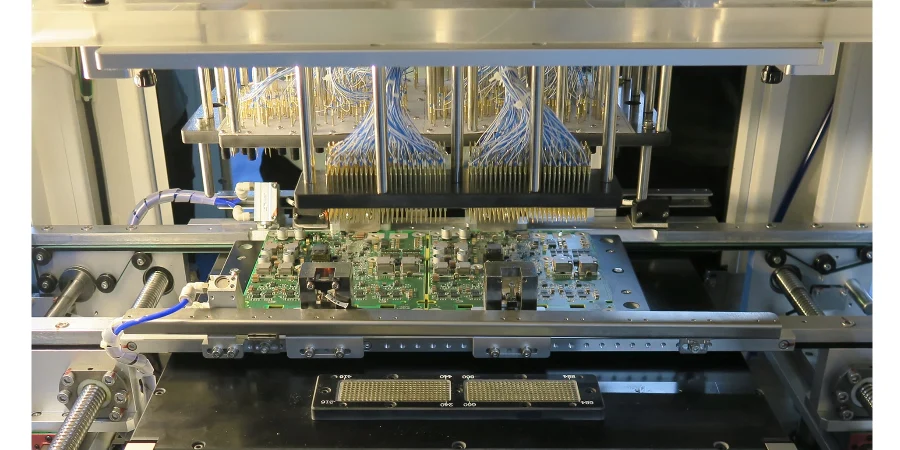
As the project enters DVT, the design stabilizes and validation becomes broader and harsher. Here, customized Fixture design (ICT/FCT) becomes essential. ICT fixtures contact predefined PCB test points using dense probe arrays to precisely measure component values (R/C/L) and detect solder defects—effectively validating SMT assembly quality. FCT fixtures go further by simulating the real operating environment: they apply inputs and observe outputs to confirm that the PCBA performs its intended functions. Data generated in this phase is key evidence that the design meets specifications and regulatory requirements.
In PVT, the production process is largely frozen and the goal is to verify mass-production stability and consistency. Efficient, robust ICT/FCT fixtures become the core tool to protect throughput and yield. A strong Fixture design (ICT/FCT) minimizes false fails, reduces manual intervention, and produces traceable test data for every PCBA shipped. This performance starts with early DFM/DFT/DFA review, where test-point accessibility, signal isolation, and mechanical fixture considerations are designed in from the beginning.
IEC 60601 core clauses: from electrical safety to fixture test strategy
The IEC 60601 family is the globally recognized “bible” for the safety and essential performance of medical electrical equipment. It defines extremely detailed requirements for electrical safety—and Fixture design (ICT/FCT) is a practical way to implement and verify these requirements on the production floor.
1. Leakage Current testing Leakage current is a core safety metric that directly impacts patient and operator safety. IEC 60601-1 defines multiple leakage-current types (earth leakage, enclosure leakage, patient leakage) and sets different limits based on equipment class (Type B, BF, CF) and normal vs. single-fault conditions. FCT fixture design must accurately emulate these conditions:
- Single-fault simulation: integrate a controllable switch matrix to simulate disconnection of neutral or protective earth.
- Precise measurement: include a standard-compliant measuring device (MD) network and high-accuracy micro-current measurement.
- Environmental simulation: because temperature/humidity affect leakage current, advanced FCT setups may link to an environmental chamber for high-temp/high-humidity validation.
2. Dielectric Strength / Hipot testing Hipot testing validates whether the insulation system can withstand transient over-voltage and prevent electric shock. The test applies high voltage (often several kV) between different electrical parts. A safe Fixture design (ICT/FCT) must address:
- Safety isolation: robust interlocks (e.g., light curtains or protective covers) so operators cannot access the DUT while high voltage is applied.
- Probes and materials: probes and fixture structural materials must have adequate voltage rating to avoid breakdown/arcing.
- Precise control: the program must control ramp-up/hold/ramp-down and accurately record breakdown current.
3. Creepage and Clearance While creepage/clearance are primarily addressed in PCB design, production processes such as Selective wave soldering or conformal coating can unintentionally reduce these safety distances. ICT cannot measure physical distance directly, but it can indirectly verify insulation effectiveness via high-voltage testing. For example, applying a voltage below Hipot but above working voltage between adjacent conductors in key isolation regions can screen insulation degradation caused by solder bridging, flux residue, or coating defects—especially for dense interconnect designs like HDI PCB.
IEC 60601 testing strategy comparison
| Test item | Purpose | Fixture design focus | Related manufacturing process |
|---|---|---|---|
| Leakage current test | Verify current through patient/operator remains within safe limits under normal and single-fault conditions. | Integrate MD networks, single-fault simulation switches, and high-precision measurement modules. | PCBA cleaning, power-module assembly |
| Dielectric strength test | Check whether insulation barriers between primary/secondary circuits and enclosure are strong enough. | High-voltage-rated materials, safety interlocks, and controlled high-voltage sources. | Transformer winding, conformal coating |
| Ground continuity test | Ensure low impedance of the protective-earth path so fuses trip quickly in faults. | Four-wire (Kelvin) probes and high-current sources. | Screw fastening, harness crimping |
ISO 10993 biocompatibility: hidden risks in fixture materials and process control
ISO 10993 focuses on the biocompatibility of materials that directly or indirectly contact the human body. While test fixtures usually do not contact patients, they can still become a cross-contamination source across manufacturing and test flows. That’s why biocompatibility risk must be considered during Fixture design (ICT/FCT).
First, fixture materials must be chosen carefully. For example, clamps used to secure wearable devices or probes may transfer harmful chemical residues to the device surface during testing, which could later contact skin. Prefer medical-grade or food-grade polymers (such as PEEK and PTFE) or passivated stainless steel.
Second, cleaning agents, coolants, and any other chemicals used during test must be evaluated to ensure they leave no bio-toxic residue on the DUT. This requires tight coupling between test and production cleaning workflows. For example, after FCT testing a thoroughly cleaned PCBA, a final cleaning step may still be needed to remove any contaminants introduced during testing.
Finally, test-environment cleanliness matters. For implantable devices or products exposed to body fluids, PCBA testing may need to occur in a controlled cleanroom. That means Fixture design (ICT/FCT) must address not only electrical performance but also cleanability, ESD behavior, and compatibility with cleanroom procedures—highlighting how medical manufacturing rigor goes far beyond consumer electronics.
Reliability validation: harsh environmental simulation beyond functional test
Medical devices—especially portable and wearable products—must remain stable across the entire lifecycle under foreseeable use conditions. One-time factory functional test is far from sufficient. Reliability validation simulates harsh environmental stress to accelerate the exposure of latent design and manufacturing weaknesses. In this process, Fixture design (ICT/FCT) shifts from a simple “referee” to a “teammate” that survives the test with the DUT.
1. Environmental Stress Screening (ESS) In the final production stage, some or all products may undergo ESS such as HALT and HASS, where the device experiences temperature and vibration far beyond its nominal spec. The fixture must:
- Withstand extremes: maintain mechanical stability and reliable electrical contact from -40°C to +125°C (or wider). Cables and probes must be rated for these extremes.
- Monitor in real time: continuously power the DUT and monitor key functional parameters during severe random vibration, capturing intermittent failures immediately.
2. Scenario-specific simulation Wearables require tests closer to real-world usage. For example, sports-monitoring products may use flexible or rigid-flex designs like Rigid-Flex PCB, requiring repetitive bending, stretching, and twisting. The FCT fixture may integrate a robotic arm or motion module to perform thousands of cycles while monitoring continuity and signal integrity. Sweat simulation (exposure to synthetic sweat) is also essential for corrosion and electrical-performance evaluation—so fixture design must resist chemical attack.
These harsh reliability tests are core work in NPI EVT/DVT/PVT and directly influence whether the product can be released. An inadequate fixture not only produces misleading conclusions—it may even damage expensive prototypes and delay the program.
Key takeaways: what makes medical-device testing different
- Safety first: the primary goal is to validate safety characteristics (e.g., leakage current, insulation), not only functionality.
- Regulation-driven: test plans and parameters must trace directly to clauses in IEC 60601, ISO 10993, and related standards.
- Lifecycle perspective: tests must consider reliability across production, transport, storage, and end use.
- Documentation and traceability: every test step and result must be documented as part of the Device History Record (DHR).
Production control and traceability: a closed-loop from DFM to DHR
In medical devices, traceability is the cornerstone of a quality management system (QMS). Regulators require manufacturers to track every component, every operation, and every test result for each unit. Fixture design (ICT/FCT) functions as a critical data-capture terminal within this closed-loop system.
1. Forward-looking DFM/DFT/DFA review An effective test strategy starts at the design source. During DFM/DFT/DFA review, HILPCB engineers work closely with customers to ensure:
- Test-point coverage: critical nets have accessible test points.
- Test-point placement: points keep safe spacing to avoid short risk and enable stable probe contact.
- Mechanical registration: the PCB includes clear fiducials (Fiducial Marks) so the fixture locates the board accurately every time. This planning dramatically improves Fixture design (ICT/FCT) efficiency and test robustness—avoiding expensive redesigns during production.
2. MES integration for traceability Modern ICT/FCT stations integrate deeply with MES. When a PCBA is loaded, the system scans its unique serial barcode. During the test, all measurement data, functional results (Pass/Fail), timestamps, and equipment IDs are uploaded in real time and bound to that serial number. This becomes a key part of the Device History Record (DHR). If a field failure occurs, manufacturers can quickly retrieve complete production and test data for root-cause analysis.
3. Data-driven continuous improvement (CAPA) Test data is not only for pass/fail decisions—it is valuable input for CAPA (Corrective and Preventive Action). Statistical analysis across large data sets reveals systemic issues, for example:
- Repeated near-limit measurements may indicate incoming component batch problems.
- High open rates in a specific area may point to placement-machine parameters or reflow profiles in SMT assembly needing optimization.
- A noticeable increase in failures after Selective wave soldering may indicate thermal damage to sensitive components. In this way, test data drives continuous optimization across supply chain and manufacturing—forming a complete quality feedback loop.
Compliance correction and optimization: HILPCB’s practical path
In real medical-device programs, it’s rare to pass every regulatory test perfectly on the first attempt. Findings are normal—the key is fast and effective correction. With extensive experience in medical PCB manufacturing and assembly, HILPCB provides full support from diagnosis through implementation.
Common issues and optimization paths
Issue 1: leakage current exceeds limits
- Possible causes: incorrect PCB material choice reduces insulation in high humidity; flux residue creates conductive paths; power-filter design issues.
- HILPCB approach: recommend high TG PCB with higher CTI; optimize cleaning and verify with ionic contamination testing; support circuit optimization, including Y-cap parameter tuning.
Issue 2: Hipot test failure
- Possible causes: insufficient creepage/clearance margin; solder splatter during SMT assembly or Selective wave soldering; bubbles or uneven thickness in conformal coating.
- HILPCB approach: identify risks early via software analysis during DFM/DFT/DFA review; optimize soldering parameters and introduce 100% AOI/X-Ray inspection; use automated selective coating to improve coating quality.
Issue 3: intermittent functional failures during vibration testing
- Possible causes: BGA cold joints; large/heavy components relying only on pads, causing stress concentration and solder fatigue cracking.
- HILPCB approach: recommend cross-section analysis or dye-and-pry testing to confirm BGA solder quality; add staking/adhesive or mechanical retention to distribute stress.
Unlike suppliers who can only provide Flying probe test, HILPCB supports deep services across NPI EVT/DVT/PVT. We’re not only a manufacturer—we’re your compliance and reliability engineering partner, combining professional Fixture design (ICT/FCT) with engineering analysis to help you take the fastest and most robust path through medical regulatory complexity.
Common Questions
Why does medical fixture design have to go beyond basic functional testing?
Because medical programs must prove more than simple pass/fail behavior. The fixture strategy has to support electrical safety, reliability, cleanliness, traceability, and compliance evidence that align with standards such as IEC 60601 and ISO 10993.
When is flying probe enough, and when do medical projects need custom ICT/FCT fixtures?
The article positions flying probe as a useful early-stage option in EVT when designs still change frequently and quick electrical feedback matters most. Once the design moves into broader validation and production readiness, custom ICT/FCT fixtures are needed to simulate real operating conditions, enforce repeatability, and support formal safety verification.
Why do fixture materials and cleaning practices matter in medical electronics?
Even if the fixture is not a patient-contact part, it can still introduce contamination, residue, or uncontrolled process variation. That makes material choice, cleanability, and chemical control part of the compliance strategy rather than an afterthought.
Why is traceability through DHR and MES so important for medical fixture design?
Medical-device manufacturing needs every unit’s test history tied to serial identity, process records, and corrective actions. Fixtures that feed structured data into DHR and MES support audits, failure analysis, and controlled release with much stronger evidence than standalone test benches.
Conclusion
In summary, the role and complexity of Fixture design (ICT/FCT) in medical imaging and wearable device development far exceeds that of traditional electronics. It is not only a tool for functional validation—it is a critical mechanism for executing IEC 60601 and ISO 10993 requirements, safeguarding product safety and reliability, and building a complete traceability system. From NPI strategy choices to mass-production data collection and process control, a well-designed fixture strategy is a foundation for medical-device manufacturers to succeed.
With deep regulatory understanding and extensive manufacturing practice, HILPCB is committed to delivering value beyond PCB manufacturing itself. Through early DFM/DFT/DFA review, we integrate test needs into the design; with professional Fixture design (ICT/FCT), we ensure every unit receives the strictest inspection; and with a complete quality system, we maintain full-process traceability. Choosing HILPCB means choosing a dependable partner to meet regulatory challenges and deliver outstanding product quality—so together we can build safer, more reliable medical devices.