
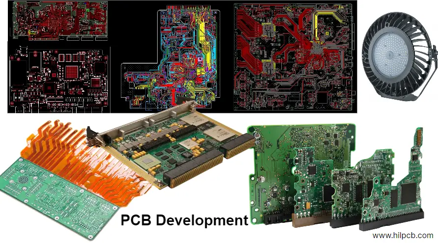
EVT, DVT and PVT are program-defined validation gates that move an industrial robot control PCB from a feasible architecture to a verified design and then to a repeatable production process. They are not certifications, fixed build quantities or substitutes for machinery risk assessment; each gate must close named risks with objective evidence.
Key Takeaways
- EVT should eliminate architecture risks: safety-function allocation, power stages, timing budgets, isolation, thermal paths and diagnostic concepts.
- DVT should verify the production-intent design against requirements, including fault injection, EMC, environmental stress, EtherCAT behavior and safety reaction time.
- PVT should prove the released design, materials, tooling, operators, programs and tests can produce conforming units without undocumented hand tuning.
- ISO 13849 Category alone does not determine Performance Level. Architecture, MTTFd, diagnostic coverage, common-cause measures and systematic controls all contribute.
- EtherCAT determinism is a system property. A controlled-impedance FR-4 stackup is usually sufficient for its 100BASE-TX physical layer; exotic laminate needs a signal-integrity reason.
- An emergency stop, watchdog or test pulse is not “safe” because the circuit exists. Its faults, timing, load behavior and transition to the defined safe state must be validated.
- Every post-freeze change needs impact analysis across safety evidence, PCB fabrication, assembly, firmware, test coverage and supply-chain approval.
Table of Contents
- What Should EVT, DVT and PVT Prove?
- Start with Robot Safety Requirements, Not a PCB Category
- Use an Evidence-Based NPI Gate Matrix
- EVT: Retire Architecture and Feasibility Risks
- DVT: Verify the Production-Intent Design
- PVT: Prove the Manufacturing Process
- Validate EtherCAT Timing Without Over-Specifying the PCB
- Design Dual-Channel Safety and Diagnostics Correctly
- Verify E-Stop, Watchdog and Output Test Behavior
- Control PCB Materials, Isolation and Power Integrity
- Build Production Test and Traceability into the Design
- Reopen Evidence When the Design Changes
- Industrial Robot Control PCB RFQ Checklist
- Reference Standards and Responsibility Boundaries
- How HILPCB Supports EVT, DVT and PVT Builds
- FAQ
- Conclusion
What Should EVT, DVT and PVT Prove?
The labels are widely used, but no universal rule fixes their quantities or deliverables. Define each gate and make its exit criteria proportional to risk.
| Gate | Question it must answer | Typical evidence | What must not be carried forward silently |
|---|---|---|---|
| EVT — engineering validation | Can the selected architecture satisfy the critical functions and risk controls? | Bring-up results, timing and power budgets, thermal measurements, early SI/PI, diagnostic prototypes, fault experiments | Unproven safety concept, unstable rails, missing isolation allocation, no test access |
| DVT — design validation | Does the production-intent design satisfy its complete requirements in intended and fault conditions? | Requirements-linked test reports, EMC/environmental results, fault injection, safety timing, reliability and pre-compliance evidence | Bench rework, temporary wiring, debug-only firmware, unexplained intermittent failures |
| PVT — production validation | Can the released process repeatedly build and test the design using production resources? | First-article records, process qualification, test coverage, yield/rework data, operator and fixture approval, traceability | Undocumented hand adjustment, uncontrolled substitute parts, unclosed deviations |
| Production release | Is the product/process baseline controlled and supportable? | Signed release package, approved deviations, change process, supply plan, quality plan and monitoring limits | Open ownership, ambiguous BOM choices, missing requalification triggers |
A gate passes on evidence, not because a build finished. Repeated resistor changes, trace cuts or manual tuning expose an unresolved design or process issue.
Start with Robot Safety Requirements, Not a PCB Category
The robot risk assessment defines safety functions and allocates them to mechanics, drives, sensors, logic, communication, power removal and the PCB.
ISO 10218-1:2025 addresses industrial robots, while ISO 10218-2:2025 addresses robot applications and cells. ISO 13849-1:2023 and IEC 62061:2021+A1:2024 provide machinery control-system routes; IEC 61508 is a foundational functional-safety series. The applicable route, edition and regional adoption must be set by the legal manufacturer and safety specialists.
Do not map “single channel” directly to PL c or “dual channel” directly to PL e. Under ISO 13849, achieved PL depends on the designated architecture plus component reliability, diagnostic coverage, common-cause failure measures and systematic behavior. Category 2 also includes a test channel and is not accurately described as a generic single-channel circuit.
Before schematic freeze, define for each safety function:
- initiating devices, modes and required safe state;
- response limit from demand to hazardous-motion control;
- diagnostics, test interval and reset/restart behavior;
- independence, common-cause and environmental assumptions;
- validation requirements and interface owners.
The PCB is one element in that chain. It cannot establish a machine-level SIL or PL by laminate choice, routing quality or a component certificate alone.
Use an Evidence-Based NPI Gate Matrix
Use a live matrix connecting requirements to physical controls, evidence and gate decisions.
| Requirement or risk | PCB/design control | EVT evidence | DVT evidence | PVT/release evidence | Change that reopens evidence |
|---|---|---|---|---|---|
| Hazardous motion after stop demand | Independent output paths, feedback and defined de-energized state | Architecture fault experiments | End-to-end reaction-time and injected-fault validation | Production test of channels and feedback | Output device, load, firmware timing or supply change |
| Loss of safety logic execution | Independent monitoring/watchdog and safe-output path | Clock/reset/watchdog concept tests | Window, timing and failure-mode injection | Programmed configuration and functional screen | MCU, oscillator, watchdog or boot change |
| EtherCAT data loss or corruption | PHY layout, link diagnostics and application timeout | Link and timing budget | Worst-case traffic, cable, topology, EMC and recovery tests | Port test and controlled firmware/configuration | PHY, magnetics, connector, stack or network cycle change |
| Common-cause channel failure | Separation, diverse resources where justified, power/clock review | Layout and dependency analysis | Coupled-fault and environmental validation | Inspection and BOM/process controls | Shared supply, routing, component or enclosure change |
| Isolation breakdown | Insulation system, creepage/clearance and approved parts | Spacing/material review | Dielectric, surge and environmental evidence as applicable | Inspection and specified electrical screen | Pollution degree, coating, altitude, voltage or material change |
| Production escape | DFT, boundary access, current/RF/functional limits | Test concept and access review | Coverage correlation and limit development | GR&R/correlation, fixture release and traceable results | Fixture, software, limit, panel or process change |
Each row needs an owner, acceptance criterion, result, deviation and baseline revision. It must also show what change invalidates the evidence.
EVT: Retire Architecture and Feasibility Risks
EVT is the least expensive time to change architecture. Prototype form factor and cosmetics are secondary to proving the hard constraints.
For a robot controller, EVT should examine:
- safety logic partitioning and freedom from interference;
- input filtering, diagnostics, independent shutdown paths and feedback;
- servo, encoder, memory, EtherCAT and scheduling budgets;
- DC-link, gate-drive, auxiliary-power, inrush and brownout behavior;
- isolation, earth, shield, chassis and worst-case thermal strategy;
- debug, programming, calibration and production-test access;
- safety and non-safety update/recovery boundaries.
Capture rail droop, clock/reset sequences and network loss, then inject plausible open, short and stuck faults. Hardware measurements must update the models.
EVT boards may contain rework and alternate footprints, yet every intervention must be logged. The DVT release package should incorporate the selected solution rather than hide an EVT patch under conformal coating.
DVT: Verify the Production-Intent Design
DVT uses the intended stackup, materials, critical components, enclosure interfaces, firmware configuration and assembly process. Its purpose is design verification and validation—not another open-ended prototype loop.
A risk-based DVT plan combines:
- functional and fault-injection tests across modes and limits;
- end-to-end safety response, restart and interlock tests;
- EtherCAT load, topology, synchronization, interruption and recovery;
- SI/PI, thermal, EMC and environmental verification;
- derating and lifetime analysis using the mission profile;
- DFM/DFA/DFT closure with production-intent panels and fixtures;
- regression after corrective ECOs.
Release limits before judging results; a timing average cannot replace a worst-case requirement. Record raw data, revisions, instruments, fixtures, conditions and anomalies.
PVT: Prove the Manufacturing Process
PVT should run with the intended factory, approved suppliers, panelization, tooling, machines, programs, operators, inspection and test flow. The sample size comes from process risk and the evidence needed; a universal quantity would be misleading.
PVT asks whether variation is controlled. Review:
- incoming identity, moisture and shelf-life controls;
- SPI, placement, reflow/selective soldering, cleaning, AOI and X-ray;
- mechanical assembly, programming, calibration and configuration verification;
- ICT, boundary-scan and functional-test coverage/correlation;
- first-pass yield, defect Pareto, rework and failure analysis;
- fixture repeatability, false failures and escape challenges;
- traceability, deviation/retest authorization and operator instructions.
Do not set a generic yield target in a blog. Establish program limits before PVT, investigate defects rather than masking them with rework, and require named approval for any open deviation. PVT is unsuccessful if output depends on one expert technician’s undocumented adjustment.
Validate EtherCAT Timing Without Over-Specifying the PCB
EtherCAT uses a 100BASE-TX physical layer, but its deterministic cycle behavior depends on the controller, slave devices, distributed clocks, topology, frame scheduling, firmware and application—not simply PCB propagation delay.
Follow the PHY vendor’s layout, impedance, magnetics, termination, return-path, isolation and ESD requirements. Control skew and discontinuities; validate MDI waveforms and link behavior on actual ports.
Standard controlled-impedance FR-4 commonly supports these short 100BASE-TX routes. Rogers/FR-4 hybrid construction is justified only when another RF or high-speed function, loss budget, thermal requirement or proven model needs it. Adding a hybrid stackup without that evidence increases material, lamination and supply risk without making EtherCAT inherently more deterministic.
Safety over EtherCAT (FSoE) is standardized in IEC 61784-3 and uses a black-channel approach. The ordinary communication channel is not treated as the safety mechanism; safety containers, certified implementations and the safety application provide the required defenses. A working EtherCAT link or a correctly routed PHY does not by itself qualify an FSoE device.
Design Dual-Channel Safety and Diagnostics Correctly
Redundancy is useful only when the channels do not share an unexamined point of failure. Review common power rails, clocks, reset lines, connectors, reference voltages, PCB contamination paths, thermal zones, software tools and output energy paths.
Cross-monitoring introduces its own failure modes. Define permitted disagreement, startup, data age, communication faults and mismatch response. Diversity can reduce some common causes while increasing verification complexity; use it only when justified.
Diagnostic coverage must come from a failure-mode analysis and verified mechanisms. Do not assign a generic percentage because the circuit has two MCUs. Latent faults, multiple faults and diagnostic independence need explicit treatment under the selected functional-safety method.
Verify E-Stop, Watchdog and Output Test Behavior
ISO 13850:2015 defines principles for emergency-stop function design. The stop behavior, reset and prevention of unexpected restart belong to the machine safety design. Two normally closed contacts can support redundancy and wire-break detection, but contact arrangement alone does not prove the complete function.
Input filtering must reject bounce/interference without violating reaction time or masking faults. Validate tolerance, thresholds, pulses and simultaneous channel disturbances.
An independent window watchdog with a direct safe-output path may detect failures an MCU watchdog cannot. Validate its service window, startup, debug, reset loop and failure response.
Output test pulses can reveal shorts or welded devices, but no universal pulse width is safe. A pulse may move a sensitive load, charge an input filter, couple into another channel or be ignored by feedback. Test the released load range, cable capacitance, input circuitry, environmental limits and worst-case timing. Fault reaction time is the measured sum of detection, logic, communication, output and mechanical stopping contributions—not a generic “tens of milliseconds” PCB specification.
Control PCB Materials, Isolation and Power Integrity
Material selection follows electrical, mechanical, thermal, environmental and supply requirements. Dk/Df stability matters for controlled impedance, but most robot-control logic does not require an RF laminate. High-Tg FR-4, heavier copper, hybrid materials or metal-backed thermal structures should each have a quantified reason.
For safety-related isolation, define working voltage, transients, insulation type, pollution degree, overvoltage category, altitude, material group, coating and applicable component standards. Creepage cannot be inferred from clearance, and a generic optocoupler voltage rating does not define the full insulation system.
Power integrity is also a diagnostic issue. A common supply dip can defeat both nominally independent channels. Separate or monitor domains where required, analyze startup/shutdown, and test simultaneous servo, relay, communication and auxiliary-load transients. Component derating must follow mission profile, manufacturer data and the reliability method; a universal 70% current rule is not evidence.
Build Production Test and Traceability into the Design
Production test should screen manufacturing defects and critical configuration errors without pretending to repeat all DVT validation on every unit.
| Test layer | Useful coverage | Limitation |
|---|---|---|
| Bare-board electrical test | Opens/shorts and specified net integrity | Does not prove assembled function |
| SPI/AOI/X-ray | Paste, placement, visible and selected hidden-joint evidence | Coverage depends on programming and geometry |
| ICT/boundary scan | Nets, components and digital interconnects with access | Cannot cover inaccessible or dynamic behavior automatically |
| Functional test | Rails, I/O channels, watchdog, communication and outputs | Must use released limits and representative loads |
| Safety production screen | Channel independence indicators, shutdown/feedback and configuration | Does not replace design-level safety validation |
Associate each serial with PCB revision, lots, critical components, firmware/configuration, test-program version, results, rework and release status. This as-built record supports containment.
Reopen Evidence When the Design Changes
A design freeze controls change; it does not prohibit improvement. Every ECO after DVT must identify affected requirements and decide what to re-run.
| Change | Evidence to reconsider |
|---|---|
| MCU, safety IC or oscillator | timing, diagnostics, FMEDA assumptions, software, EMC, thermal and production test |
| PHY, transformer or connector | SI, isolation, ESD/EMC, EtherCAT conformance and port test |
| Optocoupler, relay or MOSFET | safe state, response time, lifetime, feedback, thermal and fault behavior |
| Laminate, prepreg or copper | impedance, insulation, thermal/mechanical behavior and fabrication qualification |
| Firmware or safety parameters | requirements regression, timing, fault reaction, configuration and cybersecurity controls |
| Alternate component | electrical limits, footprint, sourcing authenticity, qualification and test limits |
| Panel, stencil, reflow or fixture | assembly yield, workmanship, correlation, coverage and traceability |
The change record should name the rationale, analysis, required verification, approvers and affected released units. “Form-fit-function equivalent” is a starting hypothesis, not automatic approval for a safety-related design.
Industrial Robot Control PCB RFQ Checklist
Product and safety basis
- Function, environment, markets, lifecycle and applicable standards.
- Safety functions, PLr/SIL allocation, safe states, response limits and validation owner.
Design package
- Gerber or ODB++/IPC-2581, drill, netlist, drawings, stackup and impedance table.
- Schematics, BOM/AVL, placement, 3D data and approved substitutions.
- Isolation, critical nets/components and channel-separation rules.
EVT/DVT/PVT status
- Current gate, open risks, prior rework, deviations and planned quantities.
- Requirements/test matrix, DFM/DFA/DFT issues and requalification triggers.
- Production-intent materials, firmware, test limits, fixtures and golden references.
Manufacturing and test
- Panelization, alloy, soldering, cleaning, coating and thermal-interface needs.
- Inspection, ICT/boundary scan, programming, FCT and safety-screen coverage.
- Fixtures, loads, network, raw data, traceability, rework and release records.
Commercial and change control
- Prototype, DVT, PVT and ramp forecast with target build dates.
- Long-lead parts, lifecycle risks, consigned material and approved alternates.
- Separate cost/lead-time effects for special stackups, heavy copper, inspection, fixtures and reports.
- ECO notification, approval, configuration control and PCN/EOL expectations.
Reference Standards and Responsibility Boundaries
Use the editions adopted by the target market and project contract:
- ISO 10218-1:2025 — Robotics, Safety Requirements, Industrial Robots
- ISO 10218-2:2025 — Robotics, Safety Requirements, Industrial Robot Applications and Robot Cells
- ISO 13849-1:2023 — Safety-Related Parts of Control Systems, General Principles for Design
- ISO 13849-2 — Safety-Related Parts of Control Systems, Validation
- ISO 13850:2015 — Emergency Stop Function, Principles for Design
- IEC 62061:2021+A1:2024 — Functional Safety of Safety-Related Control Systems
- IEC 61508 — Functional Safety of Electrical/Electronic/Programmable Electronic Safety-Related Systems
- IEC 61800-5-2 — Functional Safety Requirements for Adjustable Speed Electrical Power Drive Systems
- IEC 61784-3 — Functional Safety Fieldbuses, including Safety over EtherCAT profiles
- IPC-2221 / IPC-6012 — Rigid PCB Design and Performance Requirements
- IPC-A-610 / J-STD-001 — Electronic Assembly Acceptability and Soldering Requirements
The robot manufacturer/system integrator owns risk assessment, safety specification, validation and final release. The fabricator owns conformance to the released PCB package; the assembler/test provider owns controlled execution and traceable results within the agreed scope.
HILPCB can support PCB/PCBA DFM, fabrication, assembly and manufacturing evidence. HILPCB cannot assign machine PLr/SIL, certify a safety function, approve an FSoE implementation, determine the safe state or replace an accredited laboratory or functional-safety assessor.
How HILPCB Supports EVT, DVT and PVT Builds
Send HILPCB the current gate, risk-ranked constraints and required build evidence. A controlled build record should show what changed and what was verified.
HILPCB can review stackup and impedance, isolation geometry, heavy-current paths, panelization, component access, DFM/DFA/DFT, inspection and traceability needs. Relevant services include high-speed PCB manufacturing, heavy copper PCB fabrication, prototype assembly and turnkey PCB assembly. Submit the released package through the PCB quote request.
FAQ
What is the practical difference between EVT, DVT and PVT?
EVT proves the architecture can meet critical functions and retires feasibility risks. DVT verifies the production-intent design against complete requirements and fault conditions. PVT proves the released manufacturing and test process is repeatable using production resources. Exact quantities and names vary by organization.
Does a dual-channel robot control PCB automatically achieve PL e or SIL 3?
No. Redundancy is only one architectural input. Achieved performance depends on the applicable method, component reliability, diagnostics, common-cause controls, systematic measures, software, interfaces and validated safety function. The machine or subsystem assessment determines the claim, not the PCB layout alone.
Does EtherCAT require a Rogers and FR-4 hybrid stackup?
Usually not. EtherCAT’s 100BASE-TX physical layer commonly works on a correctly designed controlled-impedance FR-4 stackup. A hybrid laminate may be justified by another RF/high-speed function or a proven loss/thermal requirement, but it does not create deterministic behavior by itself.
What must be frozen before an industrial control PCB enters PVT?
The released design baseline should include PCB data, stackup/materials, BOM/AVL, firmware/configuration, assembly process, inspection and test programs, fixtures, acceptance limits, traceability fields and approved deviations. Later changes require documented impact analysis and scoped revalidation.
Conclusion
EVT, DVT and PVT reduce industrial robot control risk only when they are evidence gates. EVT proves the architecture, DVT verifies the design and PVT proves the process. None should pass with unexplained rework, unowned deviations or assumptions that a dual channel, watchdog, EtherCAT link or premium laminate automatically creates functional safety.
Build one traceable thread from hazard and requirement to PCB control, test result, production screen and released unit. Then reopen the affected evidence whenever hardware, firmware, material, supplier or process changes. That discipline turns a working prototype into a robot controller that can be manufactured, audited and maintained responsibly.