
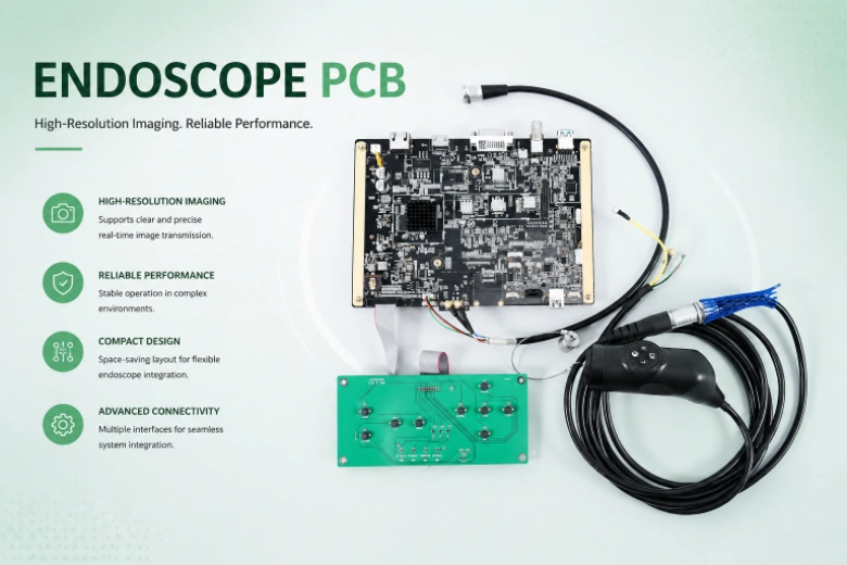
A surgical equipment PCB is a circuit assembly inside equipment used to diagnose, guide, control or deliver energy during a surgical procedure. It must implement the product’s allocated controls for basic safety and essential performance, but the PCB itself does not receive FDA clearance, CE marking or IEC 60601 certification independently from the finished medical electrical equipment.
Key Takeaways
- First identify the equipment type, applied parts, energy modality, users, environment and essential performance; “surgical PCB” is not one reusable compliance category.
- Apply IEC 60601-1 together with the relevant collateral and particular standards, such as IEC 60601-2-2 for high-frequency surgical equipment.
- Calculate creepage, clearance and insulation from working voltage, transient stress, means of protection, material group, pollution degree, altitude and construction. There is no universal 8 mm or 2.5 mm rule.
- Map each ISO 14971 risk control to a PCB requirement and verification record. A compliant component or high-Tg laminate cannot prove system safety.
- Verify electrosurgical RF energy, robot motion, endoscopic imaging, leakage current, EMC and thermal behavior at the appropriate PCBA and finished-equipment levels.
- Apply ISO 10993 biological evaluation to the finished device’s direct and indirect patient-contacting materials. An enclosed internal PCB is not automatically a patient-contact material.
- FDA’s Quality Management System Regulation became effective on February 2, 2026 and incorporates ISO 13485:2016 by reference with FDA-specific provisions.
- Ask the PCB/PCBA supplier for controlled manufacturing evidence, not unsupported claims that its process provides device approval or a complete regulatory file.
Table of Contents
- Define the Surgical Equipment Product Boundary
- Map the Applicable Medical Device Standards
- Build a Risk-Control and Evidence Matrix
- Create an Insulation Boundary Worksheet
- Design High-Frequency Electrosurgical Electronics
- Design Endoscopic Imaging and Illumination Electronics
- Design Robotically Assisted Surgical Control Electronics
- Engineer EMC and Essential Performance Together
- Control Power, Thermal and Fault Behavior
- Select PCB Materials and Patient-Contact Materials Correctly
- Integrate Design Controls, Software and Cybersecurity
- Plan Surgical Equipment PCBA Manufacturing and Test
- Create Useful Manufacturing Traceability
- Diagnose Common Surgical Equipment PCB Failures
- Surgical Equipment PCB RFQ Checklist
- Reference Standards and Responsibility Boundaries
- How HILPCB Supports Surgical Equipment PCB Programs
- FAQ
- Conclusion
Define the Surgical Equipment Product Boundary
The first engineering decision is not laminate or layer count. It is the product boundary: what the equipment does, what can reach the patient or operator, what energy it delivers and what failure would create unacceptable risk.
| Equipment family | PCB functions | Dominant hazards and constraints | Examples of additional standards to assess |
|---|---|---|---|
| High-frequency surgical generator | RF power generation, output control, return monitoring, user interface | Unintended burns, leakage, arcing, wrong energy, EMC | IEC 60601-2-2 |
| Endoscopic equipment | Image sensor/video, illumination, motors, insufflation interfaces | Heating, image loss/delay, leakage, cleaning-fluid ingress | IEC 60601-2-18 and modality-specific requirements |
| Robotically assisted surgical equipment | Motion control, encoders, brakes, force sensing, networking | Unintended motion, loss of control, collision, latency, cybersecurity | IEC 80601-2-77 |
| Surgical laser equipment | Laser control, interlocks, power, aiming beam | Excess energy, interlock failure, optical/electrical hazards | IEC 60601-2-22 and laser safety standards |
| Powered surgical tools | Motor drive, battery/charger, speed/torque sensing | Thermal injury, stall, overspeed, battery fault | Product-specific requirements and risk controls |
| Patient monitoring integrated into a surgical system | Acquisition, isolation, alarms, data interface | Incorrect or missing physiological information | Applicable IEC 60601 particular/alarm standards |
An electrosurgical generator, endoscope and surgical robot should not inherit one generic “medical PCB” checklist. Freeze the intended use, users, accessories, reusable/single-use boundaries, sterilization or cleaning processes, use environment, network connections and expected service life before allocating PCB requirements.
Map the Applicable Medical Device Standards
IEC 60601 is a series, not a single universal checklist. The general standard IEC 60601-1:2005+A1:2012+A2:2020 covers basic safety and essential performance. Collateral standards add cross-cutting requirements; particular standards modify or add requirements for a specific equipment type.
| Layer | Purpose | Surgical-equipment example |
|---|---|---|
| General | Baseline basic safety and essential performance | IEC 60601-1 Edition 3.2 |
| Collateral | EMC, usability, alarms or environment | IEC 60601-1-2:2014+A1:2020 for EMC |
| Particular | Hazards and performance unique to an equipment type | IEC 60601-2-2:2017+A1:2023 for HF surgical equipment |
| Risk/QMS/software | Lifecycle processes and evidence | ISO 14971, ISO 13485, IEC 62304 |
| Market regulation | Classification, submission, surveillance and release | U.S. FDA, EU MDR and other national requirements |
The legal manufacturer must identify the editions recognized or adopted in each market and resolve precedence. ISO 13485 certification describes a quality management system within its certified scope; it is neither product approval nor evidence that every PCB from that organization satisfies IEC 60601.
Build a Risk-Control and Evidence Matrix
ISO 14971:2019 requires lifecycle risk management for the medical device. For the PCB team, the useful output is a matrix linking hazardous situations to allocated design controls, verification evidence and change triggers.
| Hazardous situation | PCB/PCBA control | Verification evidence | Finished-equipment evidence | Change that reopens review |
|---|---|---|---|---|
| Patient/operator exposed to hazardous voltage | Insulation system, protective earth path, approved components | Layout review, dielectric/continuity screens as specified | Leakage, dielectric and single-fault tests | Supply, transformer, isolation component, coating or layout |
| Excess or unintended surgical energy | Independent inhibit, output sensing, feedback and watchdog | Channel, range, shutdown and injected-fault tests | Energy accuracy, alarm and tissue/accessory risk validation | Output stage, sensor, firmware limit or accessory |
| Loss/delay of critical image or motion data | Clock, memory, interface integrity, fault detection | SI/PI, data integrity, timeout and recovery tests | Essential-performance test under use and EMC conditions | Processor, memory, PHY, cable, software or cycle time |
| Hot surface or ignition | Current limiting, temperature sensing, thermal path | Worst-case loss and sensor fault tests | Enclosure/accessory temperature and abnormal operation | Power device, heatsink, airflow, enclosure or duty cycle |
| Wrong configuration or corrupted software | Secure boot where needed, protected settings, version control | Boot/update/configuration fault tests | System validation and cybersecurity evidence | Firmware, bootloader, key/provisioning or service process |
| Manufacturing defect escapes | DFT, controlled process, inspection and functional screen | Test coverage/correlation and limit studies | Product release and complaint feedback | Fixture, test software, stencil, process or substitute part |
The PCB supplier can supply build and test evidence, but the medical-device manufacturer owns risk acceptability, essential performance and final validation.
Create an Insulation Boundary Worksheet
The strongest differentiating asset for a surgical equipment PCB is an insulation worksheet created before layout. It prevents a single copied creepage number from being applied across unrelated boundaries.
| Boundary | Working/transient voltage | Required protection | Applied-part/operator relationship | PCB controls | Verification | Owner/change trigger |
|---|---|---|---|---|---|---|
| Mains primary to accessible secondary | Project-specific | MOOP/MOPP allocation | Enclosure/operator/patient path | Spacing, slots, insulation, transformer/opto | Dielectric, leakage, construction review | Safety engineer; supply or layout change |
| Secondary to patient-applied circuit | Project-specific | MOPP allocation | Applied-part classification | Isolation component, spacing, capacitance control | Leakage and dielectric evidence | System safety; cable/accessory change |
| HF surgical output to other circuits | Waveform-specific | Particular-standard/risk allocation | Active and return electrodes | RF spacing, shielding, sensing, isolation | HF leakage/output/fault tests | Electrosurgery team; output network change |
| Network/USB/service port to medical domain | Port-specific | System MOP allocation | External equipment connection | Isolator, transformer, shield/chassis strategy | Port dielectric, EMC and leakage | System architect; peripheral change |
| Protective earth path | Fault-current-specific | Reliable PE connection | Operator/system protection | Copper, fasteners, connector and bonding | PE continuity and fault test | Mechanical/electrical; hardware change |
Calculate clearance and creepage using the applicable standard tables and the released conditions: working voltage and waveform, overvoltage/transient category, pollution degree, material group/CTI, altitude, insulation type, number/type of means of protection, coating or solid insulation and manufacturing tolerances. Slots can increase creepage only when their geometry and cleanliness are controlled. Conformal coating does not automatically permit reduced spacing; it must be part of a qualified insulation system.
The often-repeated values “8 mm for 2 MOPP” or “2.5 mm for 1 MOOP” may appear in some conditions, but they are not universal design rules. Record the exact calculation source and revision for every safety boundary.
Design High-Frequency Electrosurgical Electronics
High-frequency surgical equipment deliberately delivers RF energy, so ordinary low-noise medical PCB advice is insufficient. IEC 60601-2-2:2017+A1:2023 applies to the basic safety and essential performance of HF surgical equipment and accessories within its scope.
Partition the board into mains/power conversion, RF generation, output matching, current/voltage sensing, return-electrode monitoring, control, UI and communication zones. Review parasitic capacitance across isolation, RF current return paths, electric-field concentration, connector/accessory limits and coupling into low-level measurement circuits.
The design and test plan should cover:
- output power and waveform over the released load range;
- independent inhibition and safe behavior after sensor/control faults;
- return-electrode monitoring where applicable;
- RF leakage, unintended current paths and capacitive coupling;
- arcing, carbonization, contamination and spacing near high-field nodes;
- thermal duty cycles, cooling faults and temperature sensing;
- accessory recognition, connection faults and wrong-accessory use;
- immunity of control, display and alarms during RF activation.
Do not use a standard continuity test to claim electrosurgical safety. RF behavior depends on the complete output network, cables, electrodes, accessories, enclosure and operating modes.
Design Endoscopic Imaging and Illumination Electronics
Endoscopic electronics combine sensitive image acquisition with high-speed digital interfaces, LEDs or other illumination, motors and long cables. The PCB must protect image integrity without allowing illumination heat or motor noise to compromise the patient-facing assembly.
Keep sensor clocks and high-speed video return paths continuous, control cable/connector impedance, and isolate switching LED drivers and motors from analog rails. Define what image corruption, freeze, latency or loss is detectable and what the equipment does when image quality is inadequate for the intended procedure.
Thermal validation must include illumination at maximum intended duty, a contaminated or restricted optical path, enclosure limits and sensor drift. For reusable systems, cleaning/disinfection and fluid ingress are finished-assembly issues that can affect connector corrosion, coating, leakage and optical performance. A bare PCB coating certificate cannot qualify the reusable endoscope.
Design Robotically Assisted Surgical Control Electronics
Robotically assisted surgical equipment adds motion hazards, distributed control, braking, position/force sensing, networking and complex software. IEC 80601-2-77 should be assessed for equipment within its scope.
Build a timing and fault budget from sensor acquisition through control computation, network transport, drive response and mechanical stopping. Identify which functions require independent monitoring or energy removal. Test encoder disagreement, stuck commands, communication delay/loss, processor reset, brake/output faults, power interruption and recovery.
The PCB architecture should separate safety-related and non-safety functions as required by the risk analysis, control shared clocks/power/resources, and expose diagnostics without creating an uncontrolled service path. A redundant bus or second MCU is not sufficient until common-cause dependencies and the complete transition to a safe state are verified.
Connected surgical systems also need cybersecurity lifecycle controls. Hardware may support secure boot, signed updates, protected identity/key storage, debug restriction and audit-capable configuration, but security depends on software, provisioning, network architecture, vulnerability handling and post-market support.
Engineer EMC and Essential Performance Together
IEC 60601-1-2:2014+A1:2020 addresses electromagnetic disturbances for medical electrical equipment and systems. It links test levels and risk management to the intended electromagnetic environment. Passing emissions does not prove immunity, and an undetected reset during immunity testing is not acceptable merely because the equipment later reboots.
Define monitored essential performance and pass/fail criteria before EMC testing. For surgical equipment, monitor delivered energy, image validity, robot motion, alarms, critical measurements, watchdog events and safe-state transitions—not only whether the display remains lit.
PCB controls include:
- continuous return paths and small high-di/dt loops;
- filtering at the connector or boundary where noise enters;
- chassis/shield termination that does not route RF current through sensitive ground;
- isolation-component capacitance included in common-mode analysis;
- ESD protection selected for both surge behavior and signal integrity;
- physical separation of RF/power switching from sensors and safety monitoring;
- test points that allow rail, clock and reset observation during immunity tests.
HDI can shorten routes and reduce size, but it is not automatically an EMC solution. Stackup, return geometry, enclosure, cables, filters, software behavior and test configuration remain decisive.
Control Power, Thermal and Fault Behavior
Create a state-based power budget for startup, self-test, standby, maximum output, simultaneous motors/illumination, charging, update and fault modes. Validate rail sequencing, droop, reset thresholds and stored-energy discharge.
Power devices, transformers, relays, shunts and connectors need mission-profile-based derating and thermal analysis. Measure component, copper, insulation and enclosure temperatures in the released mechanical system. High-Tg laminate improves glass-transition margin; it does not by itself provide electrical isolation, flame safety, high CTI or acceptable device temperatures.
Single-fault analysis may require open/short components, blocked cooling, disconnected sensors, stuck switches, incorrect accessories and failed regulators. The product team decides which faults apply and what safe behavior is required. The PCB layout must make critical shutdown paths testable and prevent a shared power/ground failure from defeating nominally independent controls.
Select PCB Materials and Patient-Contact Materials Correctly
ISO 10993-1:2025 places biological evaluation within a risk-management process for the finished medical device. Evaluation depends on the nature and duration of direct or indirect body contact, chemical characterization, processing, residues and foreseeable exposure.
An internal PCB sealed inside a console is not automatically patient-contacting. Conversely, a flex circuit, coating, adhesive, sensor, electrode or connector in a patient-contacting assembly may require evaluation as part of the exact finished construction.
Do not treat “halogen-free,” RoHS compliance, ENIG, OSP, polyimide or a supplier’s “medical grade” label as proof of biocompatibility. These describe different material or environmental attributes. Record the exact laminate, solder mask, finish, adhesive, coating, cleaning process and change controls, then let the biological-safety team determine relevance.
Material selection should instead answer measurable needs: insulation/CTI, Tg/Td, thermal conductivity, Dk/Df, moisture absorption, flex life, cleanliness, chemical exposure, sterilization/cleaning compatibility and long-term availability.
Integrate Design Controls, Software and Cybersecurity
As of February 2, 2026, FDA’s Quality Management System Regulation is effective and incorporates ISO 13485:2016 by reference with FDA-specific requirements. U.S. manufacturers should use the current QMSR framework rather than relying on an outdated summary of the former Quality System Regulation.
Design inputs allocate requirements to schematics, stackup, BOM, PCB layout, firmware interfaces and manufacturing/test specifications. Verification checks outputs against inputs; validation checks whether the finished device meets user needs and intended use. Supplier DFM reports, certificates and test data can support these records but do not constitute the entire medical-device file.
IEC 62304 addresses medical-device software lifecycle processes. Software safety classification does not automatically mandate ECC memory, redundant processors or a particular PCB; architecture comes from risk controls. Hardware watchdogs, ECC, protected boot and independent shutdown paths may be appropriate, but each mechanism needs requirements and fault-based verification.
For connected devices, use the current FDA cybersecurity expectations and IEC 81001-5-1 where applicable. Tie PCB identity, boot state, firmware and provisioning results together without storing private keys or shared secrets in ordinary production logs.
Plan Surgical Equipment PCBA Manufacturing and Test
The manufacturing control plan should reflect risk and design, not a generic promise of “zero defects.”
| Stage | Evidence | Boundary of the evidence |
|---|---|---|
| Incoming control | Approved part/material identity, lot and handling status | Certificate does not replace verification or change control |
| PCB fabrication | Stackup, material, coupon, electrical test and inspection records | Does not prove assembled or system function |
| SMT/THT assembly | SPI, placement, reflow/selective process, AOI and workmanship | Does not prove hidden-joint reliability or essential performance |
| Hidden joints | X-ray/AXI for specified BGA/LGA/QFN/thermal structures | Image interpretation needs released criteria |
| Cleanliness/coating | Process records and specified cleanliness/coating tests | Must correlate with leakage, corrosion and insulation needs |
| Structural electrical test | Flying probe, ICT and boundary scan where designed | Coverage depends on access and test model |
| Programming/configuration | Approved image, verification and lock state | Must be linked to the released unit |
| Functional screen | Rails, current, interfaces, sensors, shutdown and alarms | Does not replace complete IEC 60601/system validation |
Hipot and leakage testing should occur at the level and frequency defined by the product’s safety plan and standards. Applying an inappropriate voltage to individual electronic assemblies can damage components or create evidence that does not represent the final insulation system. Agree test nodes, ramp, limits and responsibilities before fixture release.
Create Useful Manufacturing Traceability
Traceability should answer which released inputs and process results produced a unit or lot. Depending on product risk and contract, associate:
- PCB/PCBA revision, fabrication lot and panel position;
- assembly lot and critical component manufacturer/part/lot;
- approved material and process substitutions;
- firmware, bootloader and configuration versions;
- inspection, electrical, functional and safety-screen results;
- equipment/program/fixture revision and calibration status;
- deviations, rework, retest and release authorization.
The medical-device manufacturer defines retention, device identifiers and linkage to its quality records. A PCB/PCBA supplier should provide the agreed manufacturing history; it should not claim that a batch traveler is automatically a complete Device Master Record or proof of regulatory compliance.
Diagnose Common Surgical Equipment PCB Failures
| Failure | Common contributors | Evidence to collect | Preventive control |
|---|---|---|---|
| Leakage exceeds limit | Isolation capacitance, Y capacitors, contamination, cable/accessory path | Boundary-level leakage and construction review | Insulation worksheet and controlled materials/cleanliness |
| Passes bench EMC, fails with accessories | Cable/shield/ground configuration differs | Full-system current paths and monitored functions | Test released accessories and intended configurations |
| Electrosurgical output is unstable | Load mismatch, parasitics, sensing delay, thermal drift | Output waveform, load, temperature and control logs | Validate full load/mode/duty matrix |
| Endoscopic image freezes under disturbance | Rail/reset/clock event or software timeout | Video, rail, reset and error logs during EMC | Observable fault detection and safe user response |
| Surgical robot moves unexpectedly after fault | Shared resource, stale command, brake/output dependency | End-to-end fault timeline | Independent inhibit and validated stopping path |
| Coating creates intermittent leakage | Poor cleanliness, bubbles, edge coverage or cure | Ionic/visual/cross-section and humidity evidence | Qualified cleaning/coating process |
| “Biocompatible material” becomes invalid | Grade, adhesive, process or exposure changed | Exact as-built material/contact map | Biological evaluation plus change control |
| Recall scope cannot be identified | Hardware, firmware and test records are disconnected | Traceability-system audit | One released configuration and unit/lot linkage |
Surgical Equipment PCB RFQ Checklist
Product and regulatory scope
- Intended use, equipment type, applied parts, users, environments, markets and classification strategy.
- Applicable general, collateral and particular standards with editions.
- Essential performance, risk controls, safety boundaries and final validation owner.
Electrical and PCB design
- Schematics, Gerber/ODB++/IPC-2581, drill/netlist, fabrication/assembly drawings and 3D data.
- Regional stackups, exact materials, impedance, copper, surface finish and IPC acceptance requirements.
- Working/transient voltages, MOOP/MOPP allocation, CTI/material group, pollution degree, altitude, slots/coating and spacing table.
- RF output, sensitive analog, high-speed video, motion, power, PE/chassis/shield and thermal constraints.
Components and assembly
- BOM/AVL, lifecycle/traceability requirements and approved substitutions.
- Moisture handling, paste/alloy, THT/selective soldering, cleaning, coating and thermal interfaces.
- Panelization, carriers, depaneling, press-fit/connectors, cable/accessory and mechanical constraints.
Inspection and test
- SPI/AOI/X-ray, flying probe/ICT/boundary scan and workmanship criteria.
- Programming/configuration, functional modes, loads, network/accessory fixtures and acceptance limits.
- Insulation/PE/leakage screens assigned to PCB, PCBA or final system.
- Raw-data, failure-analysis, rework/retest and correlation requirements.
Quality and commercial
- Required supplier QMS/certification scope and audit expectations.
- Lot/unit traceability, record retention, change notification and requalification triggers.
- Prototype, verification, pilot and production quantities/forecast.
- Separate pricing for special materials, tooling, coating, inspection, fixtures, testing and reports.
Reference Standards and Responsibility Boundaries
Use current, contractually applicable editions:
- IEC 60601-1:2005+A1:2012+A2:2020 — Basic Safety and Essential Performance
- IEC 60601-1-2:2014+A1:2020 — Electromagnetic Disturbances
- IEC 60601-2-2:2017+A1:2023 — HF Surgical Equipment and Accessories
- IEC 60601-2-18 — Endoscopic Equipment
- IEC 60601-2-22 — Surgical, Cosmetic, Therapeutic and Diagnostic Laser Equipment
- IEC 80601-2-77 — Robotically Assisted Surgical Equipment
- ISO 14971:2019 — Medical Device Risk Management
- ISO 10993-1:2025 — Biological Evaluation Within Risk Management
- ISO 13485:2016 — Medical Device Quality Management Systems
- IEC 62304 — Medical Device Software Lifecycle Processes
- IEC 62366-1 — Application of Usability Engineering to Medical Devices
- IEC 81001-5-1 — Health Software and Health IT Security Lifecycle Activities
- IPC-6012 / IPC-A-610 / J-STD-001 — PCB and Assembly Performance/Workmanship
Applicability depends on intended use, equipment classification, market and architecture. The legal manufacturer owns regulatory strategy, risk management, design controls, clinical/usability evidence and final release. Qualified safety, EMC, biological, software and cybersecurity specialists or laboratories own work within their competence.
HILPCB can support agreed PCB/PCBA DFM, fabrication, assembly, inspection and manufacturing records. HILPCB cannot approve a medical device, certify biological safety from a material name, determine MOPP/MOOP allocation, issue an IEC 60601 system report or guarantee clinical performance.
How HILPCB Supports Surgical Equipment PCB Programs
Send HILPCB the product boundary, released stackup, insulation worksheet, risk-ranked PCB controls, BOM/AVL, cleanliness/coating needs, traceability fields and test allocation before layout or build release. A useful review should return buildability questions, disclosed material/process alternatives, test-access gaps and documented deviations.
Relevant services include multilayer PCB fabrication, HDI PCB manufacturing, high-Tg PCB fabrication, prototype assembly and turnkey PCB assembly. Submit the controlled package through the PCB quote request.
FAQ
Does a surgical equipment PCB need IEC 60601 certification?
IEC 60601 applies to medical electrical equipment and systems within scope, using the relevant general, collateral and particular standards. A PCB supplier can build to allocated requirements and provide evidence, but the board alone is not the finished equipment certification object.
What creepage distance is required for 2 MOPP?
There is no single value for every design. The result depends on working voltage and waveform, material group, pollution degree, altitude, insulation type, construction and the applicable standard table. Record a boundary-specific calculation rather than copying 8 mm into every layout.
Must every internal medical PCB use biocompatible materials?
No. ISO 10993 evaluation follows the finished device’s direct and indirect patient-contact exposure and risk. An enclosed console PCB may have no patient contact, while an exposed flex, adhesive, coating or electrode may require specific evaluation. RoHS, ENIG or “medical grade” labels do not prove biological safety.
What should a PCB supplier provide for a medical-device submission?
The agreed package may include material identity, stackup, fabrication and assembly travelers, inspection/test results, traceability, deviations and change notifications. The legal manufacturer decides how those records support its risk, design and regulatory files; supplier records do not replace system verification or approval.
Conclusion
A surgical equipment PCB is successful when it implements clearly allocated safety and essential-performance controls and produces evidence that remains traceable through change. Start with the exact equipment and applied-part boundary, select the full standard set, calculate each insulation path, and connect ISO 14971 risks to PCB requirements and tests.
Then validate the modality that makes the product surgical: RF energy for electrosurgery, image and illumination integrity for endoscopy, or motion and stopping behavior for robotic assistance. Control materials, software interfaces, manufacturing and traceability without claiming that a premium laminate, medical label or supplier certificate approves the finished device. That discipline creates a defensible path from PCB design to system-level compliance and reliable production.