
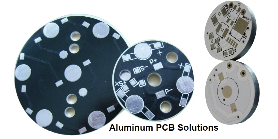
Selecting an aluminum PCB supplier requires more than confirming that a manufacturer offers MCPCB fabrication. Engineers and procurement teams should decide based on the thermal path, dielectric performance, electrical isolation, assembly capability, and production evidence. The supplier should provide a manufacturable stackup, material data, inspection records, and validation evidence that matches the application power level. The key decision inputs are dielectric thermal conductivity, dielectric thickness, copper design, aluminum base construction, flatness, and assembly control.
What should engineers evaluate before buying an aluminum PCB?
An aluminum PCB (also called an MCPCB or Metal Core PCB) replaces the conventional FR-4 core structure with a metal substrate that spreads heat away from power-generating components.
A typical aluminum PCB thermal stack is:
Copper circuit layer → Thermally conductive dielectric → Aluminum base → Heat sink or chassis interface
The actual operating temperature depends on the complete heat path:
Component junction → solder/pad → copper layer → dielectric → aluminum base → TIM → heat sink/housing → ambient environment
For LED modules, power electronics, and automotive systems, the PCB supplier decision should focus on whether the manufacturer can maintain thermal performance consistently from prototype builds through production.
What technical specifications determine aluminum PCB performance?
The aluminum base provides heat spreading, but the dielectric layer is the main engineering tradeoff. It must transfer heat while maintaining electrical isolation.
Typical industry aluminum PCB dielectric thermal conductivity ranges:
- Standard thermal dielectric: 1.0–3.0 W/mK
- High-performance thermal dielectric: 4–8 W/mK
- Standard FR-4 comparison: approximately 0.3 W/mK
Higher thermal conductivity is not automatically better. The final thermal result depends on:
- Dielectric thickness
- Thermal resistance
- Copper area and copper weight
- Component footprint
- Solder quality
- Thermal interface material (TIM)
- Heat sink attachment
- Operating duty cycle
A supplier that only quotes a W/mK value without reviewing the complete thermal path leaves a major engineering decision unresolved.
What aluminum PCB parameters create the highest project risk?
| Parameter | Typical values / design range | Risk if poorly controlled | Evidence to request |
|---|---|---|---|
| Dielectric thermal conductivity | 1.0–3.0 W/mK standard; 4–8 W/mK high-performance | Higher component temperature and reduced thermal margin | Material datasheet and thermal conductivity verification |
| Dielectric thickness | Common industry range: 75–150 μm | Thicker dielectric increases thermal impedance; thinner dielectric may reduce isolation margin | Cross-section report showing dielectric thickness |
| Finished board thickness | Typical MCPCB structures: 1.0–5.0 mm | Mechanical mismatch with heat sink or enclosure | Mechanical drawing and dimensional inspection |
| Copper weight | Common range: 1 oz–10 oz depending on design | Current capacity and heat spreading limitations | Copper thickness measurement or cross-section |
| Thermal interface | TIM thickness and mounting pressure affect final resistance | Poor heat transfer despite good PCB material | Assembly process documentation |
| Breakdown voltage | Common metal core designs: 3 kV–4.5 kV and higher depending on dielectric | Electrical safety failure in power applications | Hi-Pot test report and dielectric specification |
How should engineers select MCPCB dielectric grade by application?
The dielectric grade determines the balance between thermal transfer, electrical isolation, and cost. Selecting the correct grade early prevents late-stage stackup changes and supplier re-qualification.
| Dielectric grade | Typical dielectric thickness | Breakdown voltage range | Best application | Cost relative | Key evidence to request |
|---|---|---|---|---|---|
| Standard (1.0–2.0 W/mK) | 75–150 µm | 2–3 kV | LED lighting | 1x | Thermal conductivity datasheet, Cross-section, Hi-Pot test |
| Mid-range (2.0–4.0 W/mK) | 50–100 µm | 3–4 kV | Motor drives / converters | 2–3x | Thermal conductivity datasheet, Cross-section, Hi-Pot test, Thermal impedance per JESD51 |
| High-performance (4.0–8.0 W/mK) | 25–75 µm | 4–5 kV+ | SiC / GaN / high-power automotive | 4–6x | Thermal conductivity datasheet, Cross-section, Hi-Pot test, Thermal impedance per JESD51 |
Engineers should match the dielectric grade to the actual power density and isolation requirement rather than defaulting to the highest thermal conductivity, because thinner high-performance dielectrics reduce isolation margin and increase cost.
How do aluminum PCB and MCPCB differ?
MCPCB is the broader category. Aluminum PCB is one type of MCPCB that uses aluminum as the metal substrate.
Common MCPCB options include:
Aluminum core PCB
Best suited for:
- High-power LED lighting
- Automotive lighting
- Power modules
- Compact thermal designs
Advantages:
- Lower weight than copper core
- Good thermal spreading
- Strong balance between cost and performance
Copper core MCPCB
Used when:
- Localized heat concentration is extreme
- Maximum thermal spreading is required
- Higher material cost and weight are acceptable
Copper provides higher bulk thermal performance, but aluminum remains the most common choice for many LED and power electronics designs.
Which aluminum PCB thermal construction should be selected?
The correct construction depends on power density, voltage requirements, and mechanical integration.
Single-sided aluminum PCB
A common construction:
- Copper circuit layer
- Thermal dielectric
- Aluminum base
This structure provides the shortest thermal path and is widely used for LED boards and power conversion products.
Double-sided or multilayer metal core PCB
These designs require additional engineering review because routing, plated holes, dielectric isolation, and thermal paths become more complex.
Manufacturers may evaluate:
- Double-sided metal core structures
- Plated-through-hole insulation requirements
- Hybrid metal-backed constructions
- Heavy copper integration
How does dielectric thickness affect aluminum PCB reliability?
The dielectric layer controls two competing requirements:
- Thermal transfer
- Electrical isolation
A thinner dielectric generally reduces thermal resistance, but it must still support the required voltage and environmental conditions.
For production programs, suppliers should control:
- Dielectric material selection
- Thickness uniformity
- Bonding quality
- Lamination consistency
- Thermal cycling reliability
A board that performs well in a single prototype may fail if production variation changes the thermal path.
What manufacturing capabilities should an aluminum PCB supplier provide?
A qualified aluminum PCB manufacturer should support:
- Aluminum and copper metal core options
- Thermal dielectric selection
- Copper thickness options
- Surface finishes including ENIG, OSP, immersion silver, immersion tin, and lead-free HASL where applicable
- Flatness control
- Electrical testing
- Dimensional inspection
- Cross-section analysis
- Production traceability
Example capability ranges published by independent MCPCB manufacturers include thermal dielectric options from 0.5–8.0 W/mK, finished board thickness ranges of 1.0–5.0 mm, and registration accuracy down to 0.05 mm for certain structures. Actual capability must be confirmed against the selected stackup and supplier process.
What evidence should procurement request from an aluminum PCB manufacturer?
A supplier evaluation should include technical evidence, not only a capability statement.
Request:
- Material datasheets
- Dielectric thermal conductivity documentation
- Cross-section analysis
- Copper thickness verification
- Dielectric thickness measurement
- Electrical test records
- Thermal validation method
- Inspection plan
- Production traceability information
For high-power applications, also request:
- Thermal resistance test method
- Temperature mapping approach
- Assembly process information
- Heat sink interface recommendations
How should engineers compare aluminum PCB suppliers?
Use a decision process based on application requirements.
| Requirement | Supplier response required | Decision impact |
|---|---|---|
| Component power dissipation | Thermal target, power level, operating environment review | Determines dielectric and core selection |
| Voltage requirement | Working voltage and isolation target confirmation | Determines dielectric thickness and safety margin |
| Mechanical interface | Board outline, mounting method, flatness requirement | Prevents heat sink contact problems |
| Production quantity | Prototype, pilot, and volume capability | Determines manufacturing stability |
| Assembly requirement | SMT capability, thermal pad control, inspection options | Reduces production risk |
What should be included in an aluminum PCB RFQ package?
A complete RFQ allows suppliers to quote the correct thermal structure.
Submit:
- Gerber files
- PCB fabrication drawings
- PCB assembly drawings if assembly is required
- BOM
- Pick-and-place files
- Stackup requirements
- Copper weight requirements
- Layer count
- Board outline and mechanical drawings
- Mounting hole details
- Via drawing
- Thermal pad dimensions
- Component power information
- Voltage and isolation requirements
- Heat sink or enclosure interface information
- Target operating temperature
Request from the supplier:
- Recommended stackup
- Material datasheets
- Cross-section report
- Thermal test report or validation method
- Electrical test documentation
- Dimensional inspection report
- Assembly inspection records where applicable
How does aluminum PCB assembly affect thermal reliability?
Aluminum PCB assembly is part of the thermal design, not a separate manufacturing step.
Assembly factors that influence performance include:
- Thermal pad solder quality
- Component placement accuracy
- Reflow profile control
- Board flatness during assembly
- TIM application consistency
- Heat sink mounting pressure
High-power LEDs, MOSFETs, IGBTs, and power modules often depend on reliable thermal transfer from the component pad into the metal core.
A supplier capable of both fabrication and assembly can review the full manufacturing path instead of optimizing only the bare board.
What applications use aluminum PCBs?
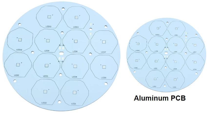
Aluminum PCB for LED lighting
Common uses include:
- Street lighting
- High-bay lighting
- Floodlights
- Automotive lamps
- High-brightness LED modules
Thermal control directly affects brightness stability, color consistency, and operating lifetime.
Aluminum PCB for power modules
Applications include:
- DC/DC converters
- AC/DC power stages
- Motor drive submodules
- Power switching circuits
The thermal structure helps move heat from switching devices into the final cooling system.
Aluminum PCB for automotive electronics
Automotive applications require:
- Stable operation across temperature changes
- Reliable thermal cycling performance
- Consistent manufacturing control
Metal core PCB selection should consider both electrical requirements and mechanical integration with the vehicle system.
How does HILPCB approach aluminum PCB selection?
HILPCB supports aluminum PCB manufacturing and assembly with engineering review focused on:
- Thermal stackup selection
- Dielectric system evaluation
- Isolation requirements
- Copper design
- Prototype-to-production transition
- Assembly considerations
For metal core PCB projects, the objective is not simply producing a board with an aluminum base. The objective is delivering a repeatable thermal path that matches the electrical, mechanical, and production requirements.
Conclusion: What is the right aluminum PCB supplier decision?
The best aluminum PCB supplier is the one that can prove control over the complete thermal system: dielectric material, thickness, copper design, metal base construction, assembly process, and inspection evidence.
For LED, power electronics, and automotive applications, engineers should select MCPCB suppliers based on measurable thermal and manufacturing data rather than a product name alone. A complete RFQ package and supplier evidence review reduce thermal failures, production changes, and long-term reliability risks.
Common Questions
Are aluminum PCBs and MCPCBs the same product?
Aluminum PCB is a type of MCPCB. MCPCB describes the wider category of metal core circuit boards, including aluminum-core and copper-core constructions.
What thermal conductivity should an aluminum PCB use?
Typical industry ranges are approximately 1.0–3.0 W/mK for standard thermal dielectric systems and up to 8 W/mK for high-performance materials. The correct selection depends on thermal load, voltage isolation, dielectric thickness, and the complete cooling path.
Why is dielectric thickness important in aluminum PCB design?
The dielectric controls both thermal resistance and electrical isolation. A thinner dielectric can improve heat transfer, but it must still satisfy voltage and reliability requirements.
Should aluminum PCB assembly be evaluated with fabrication?
Yes. Thermal performance depends on solder quality, flatness, TIM control, and heat sink integration. Bare-board performance alone does not define the final product temperature.