Electronic products are everywhere-industrial controllers, smart vehicles, servers, medical devices, consumer gadgets. None of them would work without electronics assembly, the process that transforms a bare PCB and loose components into a fully functional electronic assembly (PCBA) and finally a complete product.
This article provides a professional, end-to-end view of electronics assembly:
- What electronics assembly means in modern manufacturing
- Core process flows: SMT, through-hole, and mixed technology
- Step-by-step PCB assembly workflow
- Quality and test strategies (AOI, X-Ray, functional test, IPC standards)
- How to choose the right electronics manufacturing service (EMS) partner
Where appropriate, we’ll reference related guides and services from HILPCB, a factory that provides one-stop PCB manufacturing and assembly, from prototypes to high-volume production.
1. What Does Electronics Assembly Mean?
Electronics assembly is the process of:
- Mounting components onto a printed circuit board (PCB)
- Forming reliable electrical and mechanical connections via soldering
- Integrating PCBAs into higher-level products (box build, cable harnesses, enclosures)
- Verifying that each assembly meets electrical, mechanical, and regulatory requirements
In practice, electronics assembly covers everything from a simple 2-layer control board to complex multi-board systems with backplanes, flex boards, and high-density modules.
If you want to see how bare board manufacturing fits into this picture, HILPCB’s guide on PCB circuit board manufacturing explains the full PCB production flow before assembly.
2. What Do Electronics Assembly Manufacturers Do?
A professional electronics manufacturing service (EMS) provider typically offers:
- PCB fabrication (in-house or via qualified partners)
- SMT PCB assembly for surface-mount components
- Through-hole and mixed-technology assembly
- Turnkey PCB assembly (component sourcing + fabrication + assembly)
- Testing and programming (ICT, functional test, boundary scan, etc.)
- Box build / system integration (enclosures, cabling, final test)
For a detailed overview of these capabilities, see HILPCB’s article on PCB assembly services and their broader PCB services overview.
On the shop floor, assembly technicians and process engineers:
- Load stencils and set up solder paste printers
- Program pick-and-place machines for SMT placement
- Configure reflow and wave/selective solder profiles
- Perform AOI/X-Ray inspection and manual rework
- Execute structured testing under IPC-A-610 and related standards
HILPCB’s dedicated guide to IPC-A-610 PCB assembly standards is a good reference for what “acceptable electronic assembly” actually means in practice.
3. Core Electronics Assembly Technologies
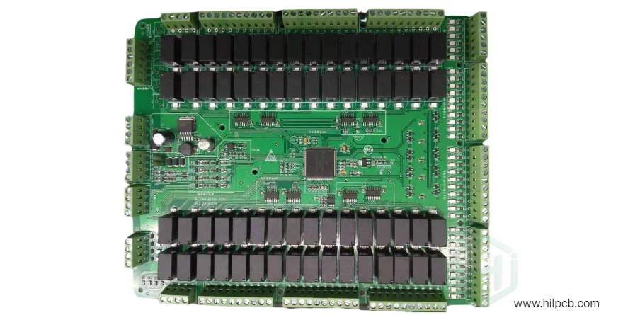
3.1 Through-Hole Assembly (THT)
Through-hole technology involves drilling holes in the PCB and inserting component leads through those holes, with solder joints formed on the opposite side. THT is still crucial for:
- High-current, high-voltage, or high-reliability components
- Connectors, transformers, relays, and large electrolytic capacitors
- Parts subject to mechanical stress (plug-in connectors, switches, etc.)
Modern THT processing uses:
- Wave soldering for large groups of through-hole joints
- Selective soldering for localized soldering on mixed-technology boards
- Skilled manual soldering for prototypes or special parts
For recommended design rules and process capability, check HILPCB’s page on through-hole PCB assembly.
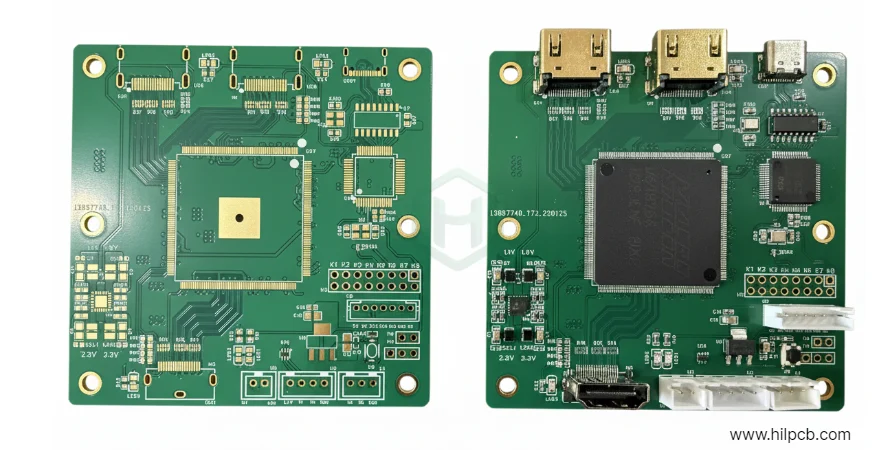
3.2 Surface Mount Technology (SMT)
SMT places components directly onto the PCB surface using solder paste and reflow soldering. SMT is the backbone of modern electronics because it enables:
- Very high component density and miniaturization
- Fine-pitch packages such as QFN, BGA, micro-BGA, CSP
- Full automation with high-speed pick-and-place machines
A typical SMT line runs:
- Solder paste printing
- SPI (solder paste inspection, optional)
- Automated pick-and-place
- Reflow soldering
- AOI and, if needed, X-Ray
HILPCB’s SMT assembly guide and the SMT production page at SMT assembly services describe these steps, including stencil design, placement accuracy and reflow profile tuning.
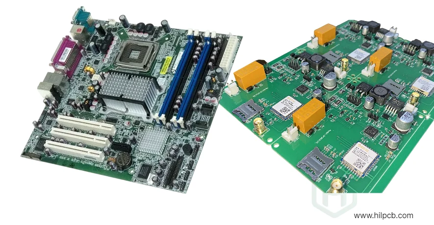
3.3 Mixed-Technology Boards
Real products almost always combine SMT with THT:
- SMT for small passive parts and ICs
- THT for connectors, power semiconductors, and mechanically strong parts
Mixed-technology lines must answer:
- SMT reflow first, then selective THT soldering, or the reverse?
- Can any components tolerate two reflow cycles?
- Where to keep solder-free zones for wave or selective soldering?
HILPCB covers such mixed processes in their DFM guidelines and large-volume PCBA manufacturing pages, showing how SMT and THT steps are sequenced in high-volume environments.
4. PCB Assembly Workflow: Step by Step
4.1 Engineering Preparation and DFM/DFA
Before the first board is built, the EMS team will:
- Import Gerber / ODB++, BOM, pick-and-place, and test requirements
- Check DFM/DFA: pad sizes, spacing, panelization, fiducials, test access, and thermal reliefs
- Suggest improvements to reduce defects and improve throughput
A good overview of this design-to-manufacturing alignment can be found in HILPCB’s PCB services: complete electronics manufacturing solutions.
4.2 Solder Paste Printing
- A stainless-steel stencil aligns against the PCB.
- Solder paste (tin/lead-free alloy + flux) is printed onto pads.
- Volume and position are critical to avoid voids, shorts, or opens.
For high-reliability builds (e.g., automotive, aerospace), paste printing is tightly controlled and often inspected using 2D/3D SPI systems.
4.3 Pick-and-Place
- Pick-and-place machines load components from reels and trays.
- Vision systems align each part and place it into the solder paste.
- Placement speed can reach tens of thousands of components per hour.
HILPCB’s SMT lines, described in the SMT assembly excellence, support ultra-fine pitch BGAs and micro-BGAs commonly found in high-density designs.
4.4 Reflow Soldering
- Boards pass through a multi-zone reflow oven (preheat, soak, reflow, cool).
- The solder alloy melts, wets pads and leads, then solidifies to form joints.
- The reflow profile must be tuned to the component mix and board thermal mass.
Special reflow profiles are often needed for temperature-sensitive assemblies such as E-ink displays or advanced sensors; HILPCB describes such tuning in their E-ink PCB assembly guide.
4.5 Through-Hole Soldering
If the design includes THT components:
- Wave soldering may be used for one-sided assemblies with many pins.
- Selective soldering or hand soldering is used for localized joints on dense SMT boards.
The throughput and process control methods for high-volume THT are discussed further in HILPCB’s large-volume PCBA manufacturing overview.
5. Inspection, Testing, and Quality Control
High-quality electronics assembly depends on systematic inspection and test.
5.1 Automated Optical Inspection (AOI)
AOI scans each assembled PCB for:
- Missing, misaligned, or rotated components
- Solder bridges, tombstones, and insufficient solder
- Polarity mistakes and wrong-value parts (when identifiable visually)
AOI is a core element in HILPCB’s IPC-compliant workflows, as outlined in the IPC-A-610 PCB assembly article.
5.2 X-Ray Inspection
For hidden joints (BGAs, LGA/QFN, stacked connectors):
- X-Ray imaging reveals voids, shorts, and insufficient solder under packages.
- It is essential for high-reliability markets such as automotive, aerospace, and telecom.
HILPCB’s article on X-ray PCB inspection explains how inline and offline X-Ray are integrated into SMT processes.
5.3 Electrical and Functional Testing
Depending on product requirements, testing may include:
- ICT / flying probe for shorts, opens, and parametric checks
- Boundary scan (JTAG) for complex digital boards
- Functional testing (FCT) with firmware programmed into the device
- Environmental stress screening (thermal cycling, vibration, burn-in) for mission-critical electronics
High-reliability flows, including test strategies for Class 2/3 boards, are summarized in HILPCB’s high-reliability PCB manufacturing and assembly guide.
6. Beyond the PCB: Box Build and System Integration
Electronics assembly doesn’t stop at the PCBA. Many EMS providers also offer box build assembly:
- Enclosure assembly and mechanical integration
- Cable harnesses, fan assemblies, displays, keypads, and connectors
- Final system testing, calibration, and packaging
This “board-to-box” path is illustrated in HILPCB’s box build assembly for electronics, where PCB assembly, wiring, and enclosures are handled under one quality system.
For customers who prefer a single partner from BOM sourcing to finished product, HILPCB provides turnkey PCB assembly that bundles procurement, fabrication, PCBA, and box build.
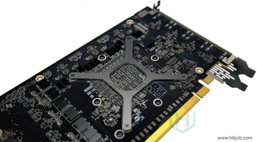
7. Special Cases: Flexible, Metal Core, and High-Density Assemblies
Modern products often require more than standard FR-4 boards:
- Flexible and rigid-flex PCB assemblies in wearables, cameras, and foldable devices
- Metal core PCBs (MCPCB) for LED lighting and high-power modules
- High-density interconnect (HDI) boards for compact, high-speed systems
Each of these has specific assembly challenges, from warpage and bending to thermal gradients and fine-pitch interconnects:
- See HILPCB’s flexible PCB assembly services for flex and rigid-flex requirements.
- For thermal and assembly nuances of metal-core designs, read the MCPCB assembly guide.
- High-density designs are discussed in high-density PCB manufacturer and assembly services.
8. How to Choose an Electronics Assembly Manufacturing Partner
When selecting an EMS partner, focus on more than just the per-unit cost.
8.1 Experience, Certifications, and Scale
- Years of operation and reference projects in your industry
- Quality certifications: ISO 9001, ISO 13485, IATF 16949, UL, RoHS, REACH, etc.
- Ability to support both prototypes and large-volume PCBA without process changes
HILPCB outlines its integrated capabilities and certifications in the broader circuit board manufacturing process guide and PCB services overview.
8.2 Technical Capabilities and DFM Support
- SMT capability (fine pitch, BGA, micro-BGA, 01005 components)
- THT, mixed technology, and special processes (conformal coating, potting, selective soldering)
- DFM/DFA support to reduce risk before production
The DFM guidelines article from HILPCB is a good checklist of what a serious EMS provider should be reviewing before building your boards.
8.3 Testing and Reliability
- AOI, X-Ray, ICT, FCT, boundary scan capabilities
- Experience with high-reliability sectors (automotive, medical, industrial)
- Proven implementation of IPC-A-610 and related standards
HILPCB’s high-reliability PCB and X-Ray inspection guides show what a mature test and inspection strategy looks like.
9. Conclusion
Electronics assembly is a multi-step, tightly controlled process that turns bare boards and components into robust, test-proven products:
- SMT and THT processes mount components with precise solder joints.
- Mixed-technology boards require careful sequencing of reflow, wave, and selective soldering.
- AOI, X-Ray, electrical and functional test ensure every assembly meets specification.
- Box build and system integration turn PCBAs into finished products ready for end users.
By partnering with a capable EMS provider such as HILPCB-offering integrated PCB manufacturing, assembly, testing, and box build-you can reduce risk, accelerate time-to-market, and ensure your electronics are manufacturable, reliable, and scalable.