
Through-Hole PCB Assembly Services
Through-hole PCB assembly services for connectors, power components, and mixed-technology boards, with wave, selective, robotic, and hand soldering, press-fit review, inspection, and testing.
Capabilities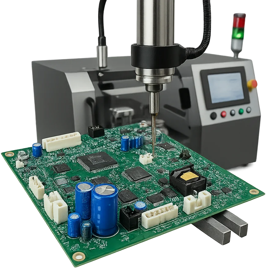
When to Use Through-Hole PCB Assembly
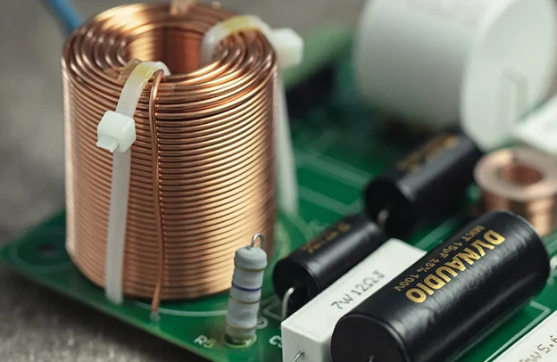
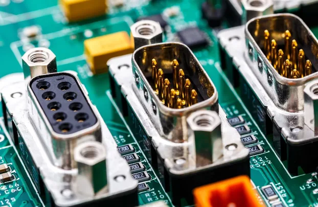
Use through-hole where mechanics and solder access matter more than component miniaturizationThrough-hole assembly is not a generic alternative to SMT. It is the right route when the board includes connectors, transformers, relays, terminals, inductors, shields, or other parts that need mechanical retention, insertion-force tolerance, or service-life robustness. Many products are mixed technology: SMT handles dense logic, while THT remains for interfaces and power hardware.
If the board is mostly fine-pitch surface mount, start with SMT assembly. If the issue is full BOM ownership, use turnkey assembly. If the deliverable includes enclosure, harness, or system test, connect this route to box build assembly.
What to send for a quote: Gerbers, BOM, placement files, drawings or photos for odd-form parts, connector datasheets, soldering restrictions, press-fit requirements, fixture constraints, test plan, and target IPC class.
- Best fit: connectors, terminals, transformers, relays, high-mass and mechanically stressed parts
- Wave, selective, robotic, hand solder, and press-fit route review
- Mixed-technology sequencing with SMT-first or selective solder planning
- Fixture, pallet, access, thermal mass, and barrel-fill review
- ICT/FCT and inspection planning based on actual THT population
🚀 Quick Quote Request
📋 Get Full Capabilities
Through-Hole Assembly Soldering and Press-Fit Options
Pick wave, selective, press-fit, or hand solder by joint population and board layoutThe first decision is route selection. Wave solder can fit broader through-hole populations when fixtures protect sensitive areas. Selective solder is better for localized joints near SMT components, heat-sensitive parts, or dense mixed-technology neighborhoods. Robotic or hand soldering supports odd-form and low-volume work. For press-fit connectors, finished-hole geometry, board support, tooling, and insertion-force limits are reviewed against the connector specification.
Inspection and test planning should be set with the route. Depending on the program, this can include AOI, X-ray sampling for barrel fill, cross-section checks, pin protrusion review, ICT, FCT, and boundary scan. Test coverage is defined from accessible nets, fixture strategy, and the approved test plan. For production programs, the same controls can feed large-volume assembly.
- Wave solder route for broader THT populations where layout allows it
- Selective solder route for localized joints near SMT or thermal-risk areas
- Press-fit review against connector and finished-hole specifications
- Fixture and access planning before release
- AOI, X-ray sampling, ICT, and FCT options by program risk
Through-Hole Assembly Technical Capabilities
Capabilities for THT, mixed-technology soldering, press-fit, and interface-heavy assemblies
| Parameter | Standard Capability | Advanced Capability | Standard |
|---|---|---|---|
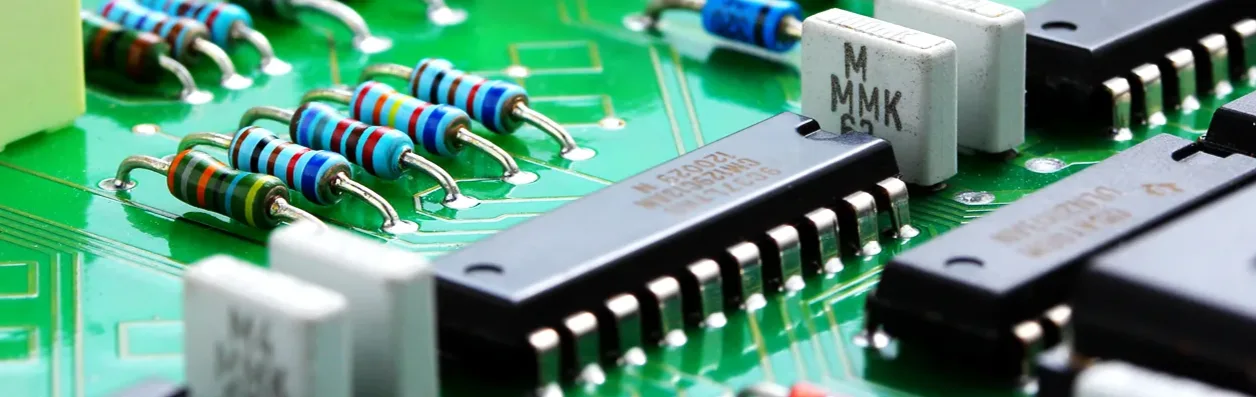
Component Types | Axial, Radial, DIP/SIP, Connectors | High-power transformers, custom heatsinks, press-fit | Component datasheet |
Soldering Process | Automated Wave Solder | Selective / Robotic / Hand Solder | IPC J-STD-001 |
Solder Alloys | Lead-free SAC305 | Sn63/Pb37, HMP (high-temp) | IPC J-STD-006 |
Max Board Size | 450 × 500 mm | 1200 × 800 mm (backplane path; engineering review) | Machine capability |
Board Thickness | 0.8–3.2 mm | Up to 12 mm (engineering review) | IPC-A-600 |
Min Through-Hole Pitch | 2.54 mm (100 mil) | 1.27 mm | Design guidelines |
Inspection Methods | Visual + AOI | X-ray (AXI), 3D AOI | IPC-A-610 |
Testing | FCT (functional) | ICT, burn-in, boundary-scan | Customer spec |
Certifications | ISO 9001, RoHS/REACH | IATF 16949, AS9100, ISO 13485 | Quality standards |
Lead Time | 5–7 days | 2–3 days express (subject to BOM and process review) | Production schedule |
Ready to start your PCB project?
Whether you need simple prototypes or complex production runs, our advanced manufacturing capabilities ensure excellent quality and reliability. Get your quote within 30 minutes.
Through-Hole PCB Assembly RFQ Requirements
Choose this page when specific components need through-hole retention, solder access planning, or press-fit review. A board with a few THT connectors is usually mixed technology, not purely through-hole.
- Good fit: connectors, relays, transformers, terminals, inductors, power interfaces, shields, press-fit parts
- Not the best fit: dense SMT-only boards, BOM ownership questions, or finished-product integration scope
- Quote inputs: Gerbers, BOM, placement, odd-form drawings, connector datasheets, solder restrictions, fixture constraints, test plan
- Adjacent pages: SMT assembly, turnkey assembly, box build assembly
Through-Hole Assembly vs SMT, Turnkey, and Box Build
- Through-Hole Assembly: use when connector, power, relay, transformer, terminal, or press-fit hardware drives the route.
- SMT Assembly: use when dense surface-mount placement and reflow are the main process.
- Turnkey Assembly: use when component sourcing, alternates, and BOM ownership are part of the ask.
- Box Build Assembly: use when enclosure, harness, firmware, and final system test are included.
Through-Hole PCB Assembly DFM and Hole-Fill Requirements
Hole-to-lead clearance of 1.5–2.0× supports wicking without excess gap; maintain annular ring ≥0.25 mm. Orient long-lead components perpendicular to wave travel to reduce shadowing/bridges. Keep selective-solder no-go zones of 3–5 mm from nearby SMT to protect reflow joints.
Specify finished hole sizes accounting for plating reduction of 50–75 μm. Add test pads ≥0.75 mm for ICT. See our DFM checklist and related SMT assembly notes for panel rails and fiducials.
Need Expert Design Review?
Our engineering team provides free DFM analysis and optimization recommendations
Through-Hole Assembly Process: Insertion, Soldering and Test
Flow: route review -> fixture or pallet planning -> lead forming and insertion -> wave/selective/press-fit or hand solder -> cleaning when required -> AOI/X-ray sampling -> ICT/FCT. The most important review points are hole geometry, component thermal mass, board support, solder access, adjacent SMT sensitivity, and acceptance class.
Through-Hole Solder Joint Inspection and Acceptance
Through-hole quality checks focus on wetting, barrel fill, bridges, voids, pin protrusion, polarity, connector seating, and electrical continuity. Acceptance is defined by the specified IPC-A-610 and J-STD-001 revision, product class, customer drawing, and quality agreement; a single barrel-fill percentage does not apply to every revision and joint condition. Agree the inspection and test plan before release so fixtures, X-ray sampling, cross-sections, and test access are available when required.
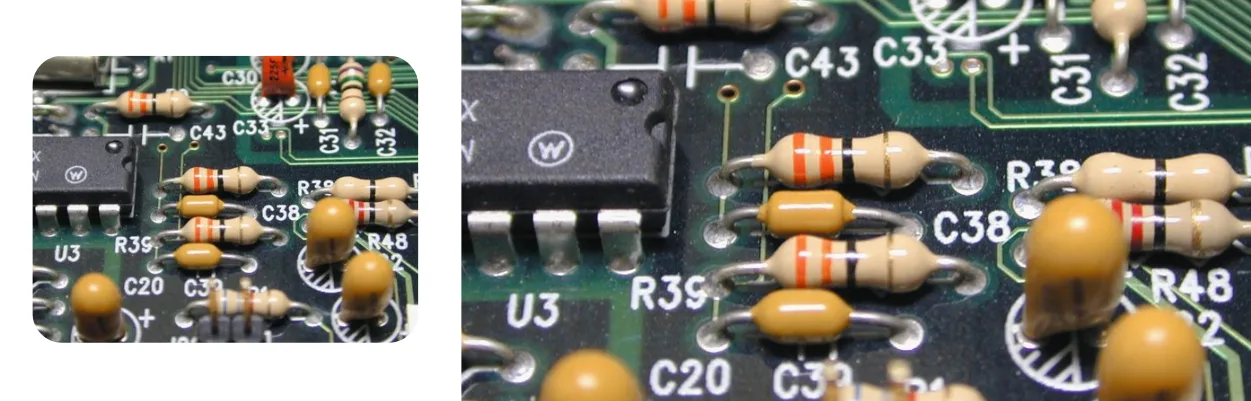
Through-Hole PCB Assembly Applications
Industrial controls (power stages, relays), automotive modules under vibration, medical devices with long service life, aerospace/military electronics needing documentation and extended traceability. For high-current rails or long service life, consider thicker copper or transition to heavy-copper PCB. When signal integrity matters, coordinate with high-speed PCB for connector launch tuning.
Through-Hole Engineering Examples for Route Planning
These common engineering scenarios show how HilPCB can choose a through-hole route around the actual component population, board mechanics, solder access, inspection plan and test requirements. Use them to prepare an RFQ; the quotation confirms the released process and deliverables.
Industrial power and control boards. Relays, transformers, terminals and high-current connectors need mechanical retention, controlled thermal exposure and reliable solder access. The review covers hole-to-lead fit, component orientation, wave or selective-solder tooling, board support, pin protrusion and electrical test access.
Automotive and mobile equipment interfaces. Connectors and press-fit parts must tolerate insertion force, vibration and repeated service handling. The route checks the connector datasheet, finished-hole condition, support tooling, insertion-force limits, seating, barrel condition and any adjacent SMT keep-out before release.
Medical and long-life industrial electronics. Mixed-technology assemblies may combine SMT logic with THT power, interface or service parts. The process can include selective solder, hand or robotic solder for odd-form parts, AOI or X-ray sampling, cross-section review and ICT/FCT when the approved test plan provides access and limits.
Through-Hole Assembly Quality Records and Certifications
Process controls: high-mix THT programs can include nitrogen wave or selective soldering, traceable profiles, press-fit tooling review, and solderability checks.
Inspection and test: workmanship can be inspected to the IPC-A-610/J-STD-001 revision and class named in the order, with ICT, FCT, boundary scan, X-ray sampling, or cross-sections selected by program risk and test access.
Quality records: MES can link material lots, travelers, inspection results, and test data. Requested deliverables such as first-article records, barrel-fill evidence, or test reports should be listed in the RFQ and quality agreement.
Certifications: ISO 9001, IATF 16949, AS9100, and ISO 13485 programs are available within the applicable certified scope; confirm project-specific requirements during quotation. See wave soldering and functional test articles for methodology.
Frequently Asked Questions
How do you choose between wave and selective soldering?
What barrel fill is required for Class 2 vs. Class 3?
How do you ensure press-fit reliability?
Can you combine SMT and THT on the same build?
What testing options are available?
What should I provide for a through-hole assembly quote?
Experience Advanced PCB Manufacturing Excellence
From simple prototypes to complex production runs, our world-class factory delivers superior quality, fast turnaround and competitive pricing. Join thousands of satisfied customers who trust us with their PCB manufacturing needs.