

An electronic-paper product combines a display panel or module with controller, power, communication and interconnect hardware. HILPCB manufactures the released rigid, flex or rigid-flex PCB and can integrate sourced components through assembly. Define whether the order covers a controller board, FPC interconnect or completed module integration; the panel's TFT backplane and electrophoretic film are separate display components.
E Ink's technology description explains bistability: a displayed image can remain after panel power is removed. The controller, radio, touch system, front light and power-converter leakage can still consume energy. Low-power display technology therefore creates an opportunity for the product power budget, rather than a guaranteed standby current or battery life from the PCB alone.
What is E-ink PCB and How Does It Work
The board supplies the selected display/controller interfaces, generates or distributes the required rails, and handles refresh commands and power states. Some modules include their own driver and power circuitry; others need a separate controller/PMIC. Release the exact panel/module and controller revisions before choosing the stackup or connector.
Core Technical Specifications to Define:
- Construction: Choose layers from actual package escape, returns, power and mechanical requirements. A 4–8-layer construction is one possible design, not an electronic-paper rule; impedance control follows the interface and edge rates.
- Power states: Measure refresh, communication, wake-up and sleep on a common battery-input basis, including leakage and conversion losses. Routing alone does not establish microamp standby.
- Display rails: Use the panel/PMIC's voltage, sequence, discharge and VCOM requirements. For a concrete device example, TI's TPS65185 datasheet lists ±15 V source-driver rails and +22 V/−20 V gate-driver rails. These are model-specific rails, not a universal 15–40 V display input or PCB rating.
- Temperature: Specify storage, operation and refresh limits for the complete assembly and selected panel, including temperature-dependent waveform handling. Do not transfer a generic −25/+85°C range to every display.
Flex PCB interconnects can support constrained packaging, but a flexible tail does not make a glass panel bendable. Specify contact side, connector pitch, pinout, finished tail/stiffener thickness, insertion direction, bend region and strain relief. HILPCB's flex route lists PI/ED-copper construction with LCP/RA options, 1–4 layers standard/up to 8 by review, and 75/75 µm standard/50/50 µm advanced geometry; confirm the combined construction after file review.
Critical Design Factors:
Follow the display vendor's waveform, temperature, reset/BUSY and full/partial-refresh guidance. Waveshare's module FAQ illustrates why partial refresh support and periodic full refresh are panel-specific; PCB routing alone does not remove ghosting. Keep converter switching loops compact, feedback/VCOM paths away from noise, and place decoupling to the selected PMIC layout rules. For TPS65185 specifically, the thermal pad connects to VN, not ground; do not apply a generic grounded-pad rule to that part.
As an explicit energy-budget example, assume controller plus display use 0.12 J of incremental energy above standby for each update, with 20 µW baseline standby and 96 updates/day. The modeled daily energy is 0.12 × 96 / 3,600 = 0.0032 Wh for updates plus 0.000020 × 24 = 0.00048 Wh standby, totaling 3.68 mWh/day. Add radio, touch, front-light and other loads outside this assumed boundary and verify the actual temperature/refresh pattern; these are not measured HILPCB values.
E-ink Display PCB Materials and Specifications
Match the material and process to the controller board and interconnect, rather than assuming a special laminate is required by the display name.
Materials and Connections:
Standard FR-4 can suit a rigid controller; high-Tg PCB construction is an option when the actual Tg/Td/CTE, reflow and mechanical requirements justify it. PI flex/rigid-flex addresses an interconnect need, not the panel's optical or environmental qualification. ACF bonding, when required by a raw-panel construction, needs its own materials, pad design, equipment/process and acceptance review; an ENIG finish alone does not establish bonding compatibility.
Manufacturing Inputs:
- Substrate: Rigid, flex or rigid-flex stackup, thickness, coverlay, stiffeners and mechanical datums.
- Finish/contacts: ENIG, OSP or another supported solderable finish based on assembly/storage needs; connector contacts must match their mating specification and wear requirement.
- Vias: Through, blind/buried or laser microvias as needed for the approved package escape and stackup. Blind vias are not all made by controlled-depth mechanical drilling, and sequential lamination is not mandatory for every board.
- Acceptance: Bare-board continuity/isolation, dimensional and workmanship checks; assembly/display functional tests are separate. Quote any impedance coupon, microsection or special fixture explicitly.
HILPCB's fabrication and assembly reviews can align imaging, drilling, lamination and panel support with the released construction. Specify a connector-based module versus a bonded raw-panel assembly before ordering tooling.
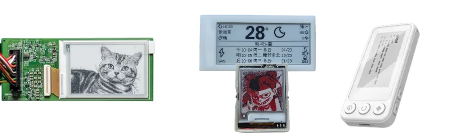
Electronic Paper PCB Assembly Process
Assembly starts with the component and panel handling limits. Reflow the controller PCBA to its qualified solder/component profile; a display panel, adhesive or FPC connector may need a different attachment stage. Do not assume a completed display tolerates the controller's reflow process.
Assembly and Integration:
SMT assembly covers standard 0201/0.4 mm packages, with finer packages by advanced review. QFP/BGA driver or controller parts, crystals, inductors and connectors need the actual land pattern, orientation, support and inspection plan. Converter parts and thermal-pad connections must follow the selected device rather than a generic display layout.
- Controllers: Exact controller/firmware/waveform revision and approved test image patterns.
- Power: PMIC/boost circuitry, rail sequence, discharge, VCOM and sleep/wake verification at defined load conditions.
- Interfaces: Selected SPI, I2C, USB or host interface, including voltage levels, reset/BUSY and actual timing requirements.
- Connectors: ZIF/FPC or board-to-board contact orientation, insertion/support, retention and cable handling.
Selected coating or underfill can address a defined environmental or mechanical need. Keep chemicals out of panel, connector, optical and service areas per vendor instructions; coating is not a universal display-life guarantee. For powered tests, supply the compatible panel, firmware, fixtures and limits for communication, image update, rail behavior and measured current. Define visual acceptance for missing pixels, contrast and residual images separately from electrical workmanship.
E-Reader PCB vs Traditional Display PCB Differences
Electronic paper suits applications where a static image and intermittent updates are useful. Unlike an LCD/OLED module with its own continuous drive and lighting behavior, the electronic-paper system needs its specific update waveform, timing and power-down sequence. Compare complete product loads and use cases, not only display technology labels.
E-Reader Technologies:
An e-reader can combine touch, storage, Wi-Fi/cellular and a front light. Page-turn cadence, network synchronization and lighting affect the battery budget. Define those modes and their measurements instead of promising weeks of operation from board construction.
Industrial Applications:
Shelf labels prioritize update frequency, radio coverage and replaceable-battery constraints. Signage and transport schedules need image-update latency, retained-image behavior during lost power/network, environmental enclosure and service access. Reflective readability depends on illumination; outdoor deployment also needs the panel's temperature, moisture and UV limits rather than a promise of perfect visibility or minimal infrastructure.
Rigid-flex PCB can fit curved housings or compact reader packaging. Confirm that the selected display itself supports any intended curvature, and define static/dynamic bend conditions for the interconnect. A folded PCB does not qualify a wraparound display.
E-ink PCB Manufacturing Cost and Lead Time
Price and schedule depend on construction, yield-sensitive features, quantity and component/panel availability. Confirm whether the order includes only the controller PCBA, the interconnect, or sourced display integration. Panel MOQ, tooling/stencil, assembly setup, firmware/fixtures, visual test time, packaging and any special bonding/qualification are distinct cost items.
Engineering and Manufacturing Route:
HILPCB can review the released stackup, connector/tail geometry, assembly access and component data before fabrication.
For eligible display builds, HILPCB offers 48–72-hour quick-turn prototypes and supports annual volumes in the millions as program capacity. Engineering support includes power optimization, signal-integrity review and component selection. Bare boards can receive 100% electrical testing with custom display fixtures; conformal coating, underfill, thermal/environmental testing and accelerated tests are available for agreed articles and conditions. These options do not establish years of field life. Turnkey assembly combines approved BOM sourcing, SMT/THT, programming and defined tests; customer-supplied or partial-turnkey sourcing can assign panel ownership separately. For a finished unit, box-build assembly can coordinate enclosure, harness and PCBA integration with the agreed test procedure.
Release Evidence:
- Bare-board electrical/dimensional checks and any specified coupons.
- First-article orientation, reflow-profile and SPI/AOI records, plus selected X-ray where relevant.
- Released firmware/waveform identity, panel/connector MPN and lot linkage, programming and defined functional/current results.
- Environmental or repeated-refresh tests only to the selected article, temperature, sequence and acceptance plan; no accelerated test automatically establishes years of field life.
Send fabrication/stackup/drill files, BOM/approved alternatives, placement and mechanical drawings, panel/controller/connector datasheets and waveform/firmware requirements. Include update modes, power/temperature limits, visual acceptance, test images/fixtures, display sourcing responsibility and packaging constraints. HILPCB can quote the confirmed fabrication, assembly and record scope with material/part availability and approval gates, including the production start condition and shipment schedule for the released build.
Frequently Asked Questions About E-ink PCB
What makes electronic-paper PCB manufacturing different from other display boards?
The selected panel/controller can require particular positive/negative rails, VCOM, power sequencing and waveform/temperature handling. Define the module boundary and FPC connection; the controller PCB is separate from the panel's TFT backplane and film.
How do you evaluate reliability and battery use for an E-ink product?
Specify actual refresh, communication, touch/light and sleep modes, temperature and usable battery capacity. HILPCB can quote assembly and defined current/functional records with supplied firmware/fixtures. Environmental and repeated-update testing need an agreed plan; a retained image or accelerated test alone does not prove multi-year system life.
What substrate materials suit electronic-paper displays?
FR-4 can suit rigid controllers, PI flex can suit interconnects, and high-Tg or specialized materials follow the actual thermal, mechanical and channel requirements. Connector/tail thickness, coverlay and stiffeners matter; the panel's bending limits are a separate specification.
Can HILPCB support consumer and industrial electronic-paper boards?
The rigid/flex fabrication, component sourcing and SMT/THT/turnkey routes can support released reader, label and signage board designs. State the actual display/module, environment, quantity, test and record scope so the construction and integration can be confirmed for that order.