
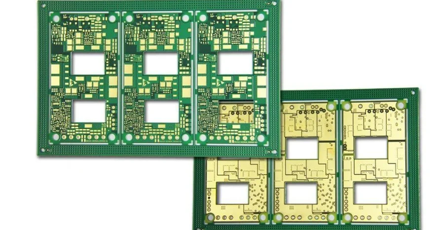
- A flow cytometer PCB should be reviewed as part of an in vitro diagnostic instrument with sensitive analog detection, high-voltage subsystems, motion or fluidics control, and strict documentation requirements.
- The first checks are detector front-end noise, high-voltage isolation boundaries, laser and motor interference paths, grounding and shielding strategy, EMC plan, and unit-level traceability for regulated builds.
- Flow cytometers in the FDA database are regulated IVD systems rather than generic lab electronics, so PCB decisions should support the final product's safety, EMC, and quality-system pathway.
- IEC 61010 and IEC 61326 families are commonly relevant to laboratory and IVD equipment, which means spacing, enclosure interfaces, cable behavior, and noise control should be reviewed as system issues early.
- Most early failures come from noisy analog front ends, weak grounding between detectors and digital processing, underdefined high-voltage isolation, or poor build records that make later validation harder to defend.
A flow cytometer PCB is the control, acquisition, and power electronics inside a flow cytometry instrument. The design usually combines detector front ends, timing and digital processing, fluidics and laser control, and high-voltage or sensitive power sections. The key engineering task is to preserve measurement integrity while keeping safety, EMC, and manufacturing records aligned with regulated instrument development.
Contents
- What to review first on a flow cytometer PCB
- Key design and validation rule table
- Early trade-off table
- How analog front ends, EMC, and isolation fit together
- How regulated build control should be planned
- What teams should freeze before pilot release
- FAQ
- Next steps
- References
- Author and review
What to review first on a flow cytometer PCB
Flow cytometer electronics are usually more mixed-signal than they first appear. The board may need to acquire weak detector outputs, manage high-voltage biasing, control pumps or valves, talk to optical subsystems, and move large data streams into digital processing.That is why the first review points are usually:
- whether the detector front end is physically separated well enough from noisy digital, motor, and switching power sections
- whether high-voltage detector bias or laser-related supplies have explicit isolation and spacing rules
- whether the grounding and shielding strategy is built around real signal-return paths instead of broad analog-versus-digital slogans
- whether cable exits, enclosure seams, and external interfaces are part of the EMC plan before prototype release
- whether the team has defined the level of traceability and build records needed for engineering, verification, and regulated pilot units
For teams still aligning the board architecture, it is usually worth reviewing multilayer PCB, high Tg PCB, and SMT assembly assumptions before release.
Key design and validation rule table
| Rule / parameter | Recommended range or decision method | Why it matters | How to verify | If ignored | | --- | --- | --- | --- | --- | | Detector front-end zoning | Keep sensitive detector inputs and gain stages away from switching and digital noise | Flow cytometry depends on preserving low-level signal integrity | Placement review and return-path review | Measurement noise dominates the useful signal | | High-voltage and isolation definition | Mark detector-bias and higher-energy sections explicitly in schematic and layout | Safety and service risk rise quickly when boundaries are vague | Schematic review, spacing review, enclosure review | Late redesign and weak safety argument | | EMC architecture | Treat cable exits, lasers, pumps, motors, and digital clocks as one EMC system | Laboratory instruments fail EMC at system boundaries, not only on traces | Pre-compliance plan and layout review | Instability appears only after full integration | | Traceability depth | Define serial, revision, calibration, and rework records before pilot | Regulated builds need reproducible evidence | Traveler and MES review | Debug and validation data become hard to trust | | Test coverage mix | Combine visual, electrical, functional, and calibration checks | Mixed-signal medical boards cannot be validated by one test method alone | DFT review and verification plan | Fault escape or incomplete evidence | | Material and assembly stability | Choose stackup and assembly flow that keep flatness, cleanliness, and solder quality consistent | Detector and precision analog behavior depend on mechanical and process stability | DFM review and pilot-build review | The board passes fabrication but drifts in system use |Early trade-off table
| Design choice | Usually stronger for | Main trade-off | What to confirm early | | --- | --- | --- | --- | | Single-board mixed system | Lower interconnect count and compact packaging | Stronger coupling risk between analog and digital sections | Detector noise budget and zoning discipline | | Split analog and control boards | Better isolation and service partitioning | More connectors and mechanical complexity | Enclosure, cost, and calibration flow | | Aggressive compact layout | Smaller instrument footprint | Harder EMC and service access | Real spacing and cable route margin | | More conservative physical separation | Better analog integrity and debug clarity | Larger board or enclosure impact | Product size target and cost limits |How analog front ends, EMC, and isolation fit together
The most important rule in flow cytometer electronics is that measurement integrity is a system outcome. It does not come from one op-amp choice or one grounding slogan.Three review questions usually matter most.
1. Is the detector path protected from local noise sources?
Photodetector front ends, transimpedance or gain stages, and ADC-adjacent analog paths are usually the first victims of layout shortcuts. If the board shares poor return paths with digital clocks, power converters, or motor drives, the measurement chain will become harder to stabilize and calibrate.
2. Are high-voltage and safety boundaries explicit?
Flow cytometers may include detector bias or other elevated-voltage sections. Those areas should be treated with clear spacing, enclosure, service, and labeling assumptions. IEC 61010-1 and IEC 61010-2-101 are relevant reference points for laboratory and IVD equipment safety strategy, so the board should support the final system design rather than leaving safety interpretation until late testing.
3. Is the EMC plan being built at board level and system level together?
IEC 61326-1 and IEC 61326-2-6 address EMC requirements for measurement, control, and IVD laboratory equipment. In practice, that means cable behavior, shielding, grounding, and placement must be reviewed with the enclosure and subsystem interfaces in mind. A Gerber viewer and PCB viewer review often helps teams spot return-path and connector issues before the first build.
How regulated build control should be planned
The board is only one part of a regulated instrument, but poor PCB build control can undermine the rest of the validation effort.ISO 13485 defines the quality-management framework commonly used for medical-device production, and ISO 14971 defines risk-management expectations for medical devices. Even if the final compliance pathway is owned by the OEM, the PCB team should still know what build evidence is needed.
A practical manufacturing and documentation plan usually includes:
- Serial-level traceability defined
Decide how board revision, component lots, programmed firmware, calibration data, and rework history will be tied to each unit. - Pilot intent defined
Distinguish engineering prototypes from validation or regulated pilot units so inspection depth matches the purpose. - Mixed-signal test path approved
Combine AOI, X-ray where needed, electrical checks, functional tests, and calibration-related verification rather than relying on one method. - Clean revision control
Freeze approved BOMs, substitutions, and firmware combinations before pilot. A BOM viewer review is often the fastest cross-check before release.
If the board needs coordinated fabrication and PCBA control, turnkey assembly, SMT assembly, and pcb prototype planning should stay in the same handoff package.
What teams should freeze before pilot release
Flow cytometer electronics become expensive to debug when the first pilot is used to answer basic architectural questions. The release package should already define what the pilot is meant to prove.A practical release checklist usually includes:
- Detector and high-voltage zoning frozen
Lock physical separation, shielding, and spacing intent for sensitive and elevated-voltage sections. - EMC architecture approved
Freeze connector placement, cable assumptions, grounding strategy, and shielding approach before build release. - Build-record requirements defined
Decide the traceability depth expected for pilot boards, including firmware, calibration, and rework. - Verification path written
Define which electrical, functional, and system-level checks the pilot must pass. - Material and assembly route confirmed
Align stackup, cleanliness expectations, and inspection flow before the first regulated build.
If the design is still changing quickly, quick-turn PCB and small-batch assembly support usually keeps the mixed-signal learning loop short.
FAQ
What is the first thing to check on a flow cytometer PCB?
Start with detector front-end zoning, high-voltage boundaries, and EMC-sensitive interfaces. Those decisions usually shape the rest of the board.
Why is flow cytometer PCB design so sensitive to layout quality?
Because the board often has to preserve weak detector signals while running digital logic, motion or fluidics control, and higher-energy power sections in the same instrument.
Do flow cytometer boards need medical-style traceability?
For regulated or validation-bound builds, usually yes. Serial-level records for revision, calibration, firmware, and rework become important quickly.
Which standards are usually relevant to this kind of instrument?
The final device pathway depends on the product and market, but IEC 61010, IEC 61326, ISO 13485, and ISO 14971 are common reference points around safety, EMC, quality, and risk management.
What should be frozen before pilot release?
Freeze the detector and high-voltage zoning, EMC architecture, build-record requirements, verification path, and material-plus-assembly route.
Next steps
If you are developing a flow cytometer or related IVD instrument, the most useful next step is usually to review detector noise, isolation, EMC, and traceability as one release system rather than as separate board-level tasks.HILPCB can support that process through:
- Multilayer PCB planning for dense mixed-signal stackups
- High Tg PCB review when thermal and process stability matter
- SMT assembly and turnkey assembly alignment for controlled medical-instrument builds
- PCB prototype and quick-turn PCB for early validation loops
- Request a quote when your layout, BOM, and pilot requirements are ready