
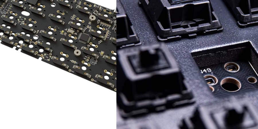
A hot-swappable mechanical keyboard PCB lets users replace switches without desoldering them. The sockets themselves are soldered to the board. This makes switch experiments and repairs accessible to enthusiasts, office users and keyboard brands, provided the switch, socket, plate and PCB were designed to fit together. Use the keyboard maker's replacement procedure and disconnect power before changing switches; “hot-swap” here describes replaceable switches, rather than permission to mate any connector under power.
HILPCB combines board fabrication with SMT assembly, through-hole assembly and component sourcing for custom keyboards. A useful manufacturing review starts with the exact socket part number and the mechanical stack, then considers solder access, support tooling and test coverage. A socket's published insertion life alone cannot establish the durability of the finished keyboard.
Hot-Swappable Keyboard PCB Architecture and Socket Integration
The keyboard circuit board must leave room for socket bodies, switch guide posts, stabilizers, LEDs and enclosure supports. Check these items together:
- Socket lands and solder-mask openings against the supplier's drawing, including its viewing direction.
- Matrix traces, diodes and test access around overlapping socket and stabilizer footprints.
- Ground references and return paths for the controller, USB interface, LEDs and any wireless circuitry.
- Plate-to-PCB spacing, switch seating height and bottom-case clearance beneath the socket.
- Alternative layouts for physical collisions, exposed contacts and unpopulated pad clearance.
- Board support near insertion points so a bent switch pin does not drive the socket away from the board.
A two-layer board can suit a straightforward matrix; a multilayer PCB offers more routing and reference-plane options for dense RGB, USB and wireless designs. Copper weight follows current, routing and fabrication requirements. Specifying 2 oz copper does not by itself prevent pad lifting, and vias near a pad do not replace mechanical support.
Optical keyboards need a compatible emitter/detector arrangement, switch geometry and firmware. They are a different sensing architecture from an MX contact socket. Removable optical switches do not establish zero system latency or compatibility with mechanical sockets.
Manufacturing the Socket and Controller Assembly
For an SMD socket, land pattern, paste volume, coplanarity and board support affect the solder joint. The socket's reflow and cleaning limits must also fit the controller, LEDs and other components. HILPCB's SMT route includes stencil and land-pattern review, SPI and AOI; placement acceptance is defined for the actual assembly rather than inferred from a machine's reference accuracy.
Through-hole receptacles need a finished plated-hole specification that fits their barrel and soldering method. HILPCB's through-hole assembly routes include selective, wave and hand soldering, selected for the component population. Open receptacles need process controls that keep solder and flux out of the spring contacts. Hand assembly is an option, not an inherent requirement of every Mill-Max design.
ENIG is one available PCB finish for flat solder lands. The receptacle's internal contact plating is a separate component specification: choosing ENIG for the board does not gold-plate the socket contacts. Likewise, laminate Tg concerns thermal behavior; board stiffness also depends on thickness, outline, cutouts and how the plate and enclosure support it.
Socket Technology and Durability Engineering
HilPCB can support Kailh, Mill-Max and Outemu socket integration and sourcing, with compatibility, lead-time and reinforcement review for the selected switch/socket combination. Fixture development and force, contact-resistance, swap-cycle or accelerated-life testing can be scoped to an agreed profile. Qualified placement to ±0.05 mm, rigid-flex constructions, and custom colored, black-core or clear-mask options are available for suitable designs; clear solder mask is distinct from transparent substrate, and these options do not promise a universal insertion life or compatibility across every socket model.
Socket Types and Applications
Kailh-style rear-mounted SMD sockets support automated assembly, while individual Mill-Max receptacles fit selected through-hole designs. Outemu-type sleeves can suit cost-sensitive products when the intended switch pins fit. Choc and other low-profile sockets use their own geometry. None of these family names is a substitute for a controlled part number.
The table provides drawing checks, not interchangeable footprints. The inch dimensions below are supplier mounting-hole callouts, not drill-tool diameters; the fabrication drawing must define the finished hole and tolerance after plating.
| Socket Model / Family | Mounting Type | Hole / Footprint Reference | Height / Clearance Check | Published Durability Reference | Assembly & DFM Precaution |
|---|---|---|---|---|---|
| Kailh MX | Rear SMD socket | Use the selected part's land pattern, stem opening and guide-hole map | Check socket body against case, foam and plate spacing | Legacy CPG151101S11 literature states 100 cycles; CPG151101S11-16 specifies 5,000 under its test conditions |
Control the exact suffix and revision in the BOM; support the PCB during insertion |
Kailh Choc V1 (CPG135001S30) |
Rear SMD socket | Use its own asymmetric layout; do not copy an MX footprint | Verify low-profile switch, plate and LED clearance together | Rev. D specifies a minimum 100-cycle no-load life test | Confirm orientation and approved soldering/cleaning conditions |
Mill-Max 0305 |
Solder-mounted receptacle | Catalog calls out 0.059–0.061 in (about 1.50–1.55 mm) mounting hole |
Drawing shoulder is 0.025 in (about 0.64 mm); barrel length differs among -0, -1 and -2 |
Select the exact part's contact and durability specification | Specify finished PTH tolerance and keep solder out of the open contact cavity |
Mill-Max 7305 / 3305 |
Low-profile solder-mounted receptacle | 7305 catalog: 0.060 in minimum; the 3305-1-15-80-47-27-10-0 datasheet lists 0.062 in |
7305 catalog shoulder: 0.014 in (about 0.36 mm); check the chosen 3305 variant separately |
The cited 3305-1 datasheet specifies 1,000 cycles minimum, subject to mating-pin and application conditions |
Do not merge series or suffixes into one hole/height specification; check pin engagement and under-board clearance |
| Outemu-type thin-pin sleeve | Model-dependent through-hole sleeve | Obtain the exact sleeve drawing and switch-pin dimensions | Check seating and plate retention with physical samples | Obtain the selected model's rating | A similar switch housing does not prove pin compatibility; choose matching parts rather than filing pins to force a fit |
Sources: Kailh legacy socket information, MX -16 specification, Choc specification, Mill-Max catalog, printed pages 177 and 179, and Mill-Max 3305-1 manufacturer datasheet.
PCB Reinforcement Strategies
- Support the load path. Use the plate, enclosure standoffs and approved assembly tooling to limit local PCB bending. Check flexible or gasket-mounted designs in their assembled condition.
- Match lands to the socket. Preserve the supplier's solderable area and clearance. Teardrops can help trace transitions where appropriate, but cannot guarantee that an overloaded socket will stay attached.
- Choose the board construction deliberately. Thickness and cutouts affect flex; copper weight also affects etching, thermal mass and soldering. High-Tg material is not automatically a stiffer board.
- Validate representative assemblies. Cycle the intended switch/socket combination with the real support arrangement. Record contact behavior, solder-joint and pad condition, insertion method and acceptance limits.
For an illustrative service-use target, one switch change per week for five years means about 260 replacement cycles per position (1 × 52 × 5). That is already above a 100-cycle component rating. It is a reason to select and validate a different socket, rather than extrapolate a lifetime from its brand name. A 5,000-cycle connector rating still does not demonstrate that every PCB pad, switch pin and mounting arrangement will survive that many replacements.
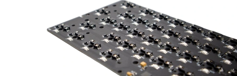
Applications and Market Segments
Different keyboard projects put different constraints on the same socket decision:
- Enthusiast custom builds: frequent switch changes, unusual layouts and access for repair.
- Entry-level keyboards: component cost and compatibility with a clearly identified switch family.
- Office and productivity keyboards: stable key mapping, serviceability and consistent feel after assembly.
- Experimental and prototype designs: alternative layouts and replaceable parts, with collision checks before each revision.
- Gaming keyboards: matrix scanning, firmware, USB behavior and LED power alongside mechanical durability.
- Mass-production consumer models: approved socket substitutions, repeatable assembly and a defined functional test.
- Premium and boutique keyboards: plate fit, appearance and low-profile clearance as well as receptacle cost.
Wireless models also need an antenna keepout that accounts for the plate, battery, cable and case. Split and ergonomic products can use cabled boards, flex interconnects or rigid-flex construction; compare assembly access and the intended bend arrangement before selecting the interconnect.
Sourcing, Assembly and Test Planning
HILPCB's turnkey assembly service connects BOM sourcing, mixed SMT/through-hole assembly and testing. For keyboard production, the purchasing data should identify approved socket suffixes, packaging, switch samples and substitution rules. A visually similar replacement socket can change the hole fit, insertion force or required stencil.
A useful test plan separates the checks:
- Bare-board electrical test: opens and shorts against the netlist before components are fitted.
- Assembly inspection: socket orientation, seating, accessible solder joints and component polarity.
- Programmed functional test: each intended key position with the released firmware, plus USB, LEDs and wireless functions that are in scope. A flying-probe net test alone cannot demonstrate all key behavior through a populated controller and matrix.
- Durability qualification: agreed samples, swap count, switch pins, force/contact measurements and failure criteria. This is a separate qualification activity, not an automatic test on every shipped keyboard.
For example, a 104-key layout with two individual receptacles per switch requires 208 receptacles before spares. Compare that placement and inspection effort with 104 integrated sockets, then include tooling, sourcing and test costs in the quotation. This is a part-count comparison, not a prediction that one route will always be cheaper.
Assembly support can also cover orientation drawings, soldering access and socket-replacement procedures. Ask for the proposed test coverage and any fixture or sample requirements before releasing the production order, particularly when the assembled plate hides the socket joints.
Aesthetic and Material Options
A visible PCB can contribute to the product's appearance through solder-mask color, silkscreen, exposed finish and the placement of RGB LEDs. Specify the visible surfaces, reference color or sample, acceptable variation and cosmetic inspection area alongside the electrical data. Confirm the requested mask and finish with HILPCB during the fabrication review.
Material and Color Choices
Colored solder mask changes the board's appearance, but clear mask does not turn ordinary glass-reinforced FR-4 into a transparent substrate. A black mask is also different from a black-core laminate. If a transparent or dark-core construction is essential to the product, identify the actual material and have its availability, optical appearance and fabrication suitability reviewed before layout release.
For RGB builds, evaluate the assembled light path: switch housing, LED orientation, plate apertures, mask and case all affect the result. A visual sample can resolve color and light-leak questions that a rendered PCB image cannot. Choose laminate grade for the assembly and operating requirements, rather than assuming a premium color or high Tg gives greater rigidity.
Suitable builds can use qualified high-Tg FR-4 or reinforced-composite substrates as separately scoped options; matte and gloss are finish choices, not substrate types. Availability and suitability depend on the selected material and build, and high Tg alone does not establish rigidity.
Integrating Appearance with the Keyboard
Match silkscreen contrast and visible copper to the case, keycaps and backplate. Keep decorative openings and exposed copper away from electrical and mechanical keepouts. Approving a first article with the intended LED, switch and plate can settle both fit and appearance before a larger build.
Manufacturing a Hot-Swap Keyboard with HILPCB
HILPCB offers PCB fabrication, controller/LED SMT assembly, through-hole assembly and turnkey sourcing. The SMT service supports SPI/AOI and test options based on the assembly's access and customer test plan. Workmanship follows the IPC-A-610/J-STD-001 revision and class named in the order under the applicable ISO 9001 quality scope; an acceptance class is not a separate product certification.
Send Gerber or ODB++ data, the drill and fabrication drawing, BOM with full socket part numbers, placement files, firmware/test instructions and the switch/plate/case mechanical stack. Include the expected replacement frequency, any RGB or wireless requirements, appearance references and prototype/production quantities. Physical switch and socket samples are especially useful when a new combination has not yet been validated.
Use the quotation review to agree on the fabrication and assembly route, component substitutions, first-article fit checks and functional-test scope. If swap-life or force testing is required, define the samples and acceptance criteria so it can be scoped separately from production continuity and workmanship inspection.
Frequently Asked Questions – Hot-Swappable Keyboard PCB
What are the main advantages of a hot-swappable PCB?
Switches can be replaced with the appropriate puller and no soldering iron. The socket remains soldered to the PCB, while the switch housing and plate provide mechanical support according to the design. This helps with customization and service; repair cost still depends on whether the fault is the switch, socket or board.
How many insertion cycles can a hot-swap keyboard PCB handle?
Use the exact socket specification. Kailh's legacy MX information states 100 cycles, while its CPG151101S11-16 specifies 5,000 under defined test conditions. The cited Mill-Max 3305-1 datasheet lists 1,000 minimum, with application-dependent life. These are component ratings; the finished keyboard needs validation with its actual pins, joints and support.
What is the difference between Kailh and Mill-Max sockets?
A rear SMD socket provides an integrated contact assembly suited to automated placement. Individual Mill-Max receptacles use plated holes and require control of hole fit, insertion and solder contamination. Compare the full part numbers, board height, quantity and assembly route; neither family name alone establishes better durability or lower total cost.
Can one hot-swap PCB support multiple switch types?
Only when its socket contacts and mechanical layout support those types. MX, Choc and optical architectures are not interchangeable. For MX-style switches, check pin dimensions, guide posts, housing, LED clearance and plate fit. Three-pin versus five-pin usually describes the presence of additional plastic guide posts, not a change from two to five electrical switch contacts.
How can I prevent socket damage?
Disconnect power, inspect and straighten bent switch pins, align the switch and insert it without forcing it. Follow the keyboard maker's procedure and support the board where required. Plate fit, standoffs and accessible socket support matter alongside sound solder lands; a larger copper pad cannot compensate for an incompatible pin or excessive force.
Are hot-swap sockets compatible with illuminated switches?
Check the complete combination. A PCB-mounted SMD LED needs a clear optical path through the switch housing, while a switch with separate LED leads may need extra holes or contacts. Socket orientation and north/south LED placement can affect housing, keycap and plate clearance. Approve the intended switch and LED on a mechanical sample rather than assuming all three-pin or five-pin switches fit.