
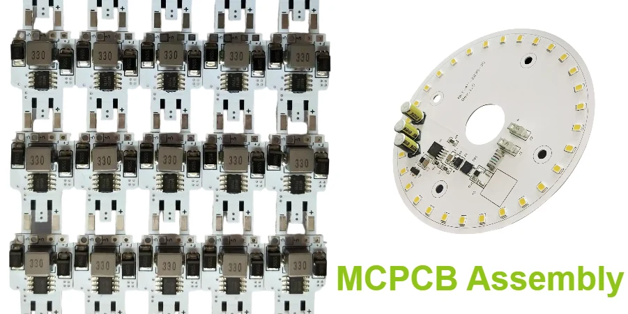
- MCPCB assembly should be reviewed as a thermal-process and insulation-control problem, not as ordinary FR-4 SMT with a metal base.
- The first checks are base-material type, dielectric limits, board thermal mass, solder-profile strategy, component heat path, and what must still be measurable after assembly.
- Most failures come from under-heated joints, warped profile assumptions, overstressed dielectric regions, trapped heat under power parts, or late mechanical changes that alter the real thermal path.
- Process success usually depends on matching stencil design, reflow energy, fixture support, and inspection method to the actual metal-core stackup before the first pilot run.
- For LED, power-conversion, and outdoor modules, assembly planning has to stay aligned with thermal validation, not only cosmetic solder appearance.
MCPCB assembly is the process of soldering and validating components on a metal-core PCB, usually aluminum-based or copper-based, where the substrate improves heat spreading but also changes how the board absorbs and releases reflow energy. The practical engineering problem is balancing solder-joint formation, dielectric protection, and thermal performance in the finished product.
Contents
- What to review first on an MCPCB assembly
- Key process and validation rule table
- Early engineering trade-off table
- How thermal mass changes stencil and reflow decisions
- How insulation, attachment, and heat path affect reliability
- What pilot-build teams should freeze before release
- FAQ
- Next steps
- References
- Author and review
What to review first on an MCPCB assembly
An MCPCB is not just an FR-4 board with better heat dissipation. The metal base changes thermal mass, board stiffness, fixture behavior, and the effective heat path after assembly. IPC's assembly standards define solder acceptability and process control at the joint level, but the board-level risk on an MCPCB comes from how the soldering process interacts with the substrate and dielectric structure.The first review points are usually:
- whether the board uses aluminum, copper, or another insulated metal substrate and what dielectric structure separates copper from the base
- whether the heaviest thermal components can actually reach a valid soldering window without overheating nearby parts
- whether the LED, MOSFET, driver, connector, or power package footprint still supports both solderability and heat extraction
- whether the fixture, carrier, or support method prevents tilt or uneven heating during print, placement, and reflow
- whether inspection and functional test still prove the real thermal and electrical behavior after assembly
For thermal designs, it is usually worth aligning metal core PCB, heavy copper PCB, and SMT assembly assumptions before prototype release.
Key process and validation rule table
| Rule / parameter | What to check first | Why it matters | How to verify | If ignored | | --- | --- | --- | --- | --- | | Substrate thermal mass | Confirm the actual board mass and heat-sinking effect before profiling | Metal-core boards absorb reflow energy differently from FR-4 | Thermal profiling on the real assembly | Cold joints or uneven wetting | | Dielectric protection | Review where heat, pressure, and rework stress sit relative to insulated regions | Thermal abuse can damage insulation performance even if solder joints look acceptable | Stackup review and process-window check | Hidden dielectric damage and field failures | | Stencil and paste strategy | Match paste volume and aperture design to pad geometry and heat demand | Thermal parts often need different print behavior than small control parts | Print inspection and pilot paste study | Insufficient solder or bridging | | Carrier and support | Decide whether the board needs support tooling during print and reflow | Rigid metal-core boards can still tilt or distort process consistency if support is weak | Trial run and machine setup review | Placement errors and inconsistent joints | | Heat path after soldering | Check how the assembled board transfers heat into chassis, sink, or enclosure | Good soldering is not enough if the final heat path is incomplete | Thermal review and powered evaluation | Hotspots and reduced service life | | Inspection method | Freeze AOI, X-ray, functional test, and thermal verification scope early | Power and LED boards often need more than visual joint acceptance | Inspection plan and validation checklist | Defects escape into pilot builds |Early engineering trade-off table
| Design choice | Usually stronger for | Main trade-off | What to confirm early | | --- | --- | --- | --- | | Aluminum-core board | Cost-sensitive thermal management in LED and industrial designs | Lower thermal performance than copper-base options in some cases | Real heat load and enclosure interface | | Copper-base board | More aggressive heat spreading and high-power density | Higher cost and heavier process burden | Whether the extra thermal margin is truly needed | | Single-pass reflow | Simpler assembly flow | Harder to optimize when thermal masses vary strongly | Component mix and board symmetry | | Carrier-assisted process | Better planarity and more stable handling | Extra tooling and setup complexity | Panel method and production volume | | Larger solder volume for power parts | Better joint formation on high-thermal-mass pads | Can raise voiding or shape-control risk | Package geometry and inspection criteria | | Added interface pad or mechanical clamp | Better final heat transfer into housing | More assembly coordination required | Chassis plan and service method |How thermal mass changes stencil and reflow decisions
The main assembly mistake on MCPCBs is assuming the profile can be tuned the same way as a standard FR-4 board. It usually cannot. The metal base pulls energy out of the soldering process, and that changes how quickly different zones heat up.Three decisions usually matter most.
1. Profile on the real board, not on a generic recipe
Indium and Kester both emphasize that solder-paste profiles should follow the paste supplier and assembly context rather than a copied oven setting. On MCPCBs, the real board mass and component mix change the result enough that coupon-only assumptions are rarely sufficient.
2. Treat heavy thermal pads and small signal parts as one shared process window
High-power LEDs, drivers, and thermal pads may need more energy, but nearby small components can still be overexposed if the window is stretched carelessly. Stencil tuning, placement sequence, and fixture support often matter as much as peak temperature.
3. Plan for measurement before arguing about optimization
If thermal profiling is not performed on the actual build condition, teams often debate reflow settings without knowing whether the limiting issue is cold solder, poor contact, warped support, or simply the wrong heat path assumption.
How insulation, attachment, and heat path affect reliability
Reliable MCPCB assemblies are not judged by solder appearance alone. They are judged by whether the board can carry electrical load while moving heat out of the active area without degrading the insulated structure.The main engineering checks are:
- whether the dielectric between copper and metal base is appropriate for the operating voltage and environment
- whether heavy components create concentrated stress during thermal cycling
- whether screws, clips, thermal pads, or interface materials change board flatness or local heat extraction after assembly
- whether rework or manual touch-up could damage insulated areas or weaken long-term consistency
If the design combines thermal management with dense assembly, turnkey assembly, PCB prototype, and BOM viewer review usually needs to happen together.
What pilot-build teams should freeze before release
An MCPCB pilot succeeds when the thermal target, assembly target, and validation target are all frozen together before the first build.A practical release checklist usually includes:
- Base material and dielectric approved
Confirm the exact metal-core construction before stencil and profile work begins. - Thermal profile validated on the real assembly
Use the actual board and key components rather than a generic lead-free profile assumption. - Heat path documented
Define how heat leaves the assembly in final use, not only during soldering. - Carrier or fixture plan approved
Freeze any support tooling needed for print, placement, or reflow stability. - Inspection plan defined
Decide which solder, thermal, and electrical checks are required for pilot acceptance. - Component and interface materials reviewed
Use a BOM viewer review to catch substitutions that alter thermal or attachment behavior.
If the heat path is still changing, quick-turn PCB support is usually more useful than forcing a premature production-style run.
FAQ
Why is MCPCB assembly harder than standard FR-4 assembly?
Because the metal base changes how the board absorbs reflow energy, supports the assembly mechanically, and transfers heat after soldering.
Does an MCPCB always need a different reflow profile?
Usually yes in practice, because the board thermal mass and package mix often differ enough from FR-4 that a copied profile is unreliable.
Is solder-joint appearance enough to judge a good MCPCB build?
No. Thermal performance, insulation protection, and final attachment to the enclosure or heatsink also need to be verified.
What is the biggest reliability risk on assembled MCPCBs?
Often it is the mismatch between solder-process assumptions and the real thermal path, which can create hidden stress, weak joints, or persistent hotspots.
What should be frozen before the first pilot run?
Freeze the metal-core construction, profile approach, support tooling, inspection method, and final heat-transfer assumptions.
Next steps
If you are preparing an LED, power, or outdoor thermal board, the most useful next step is usually to review metal-core construction, solder profile, and finished heat path together before pilot release.HILPCB can support that process through:
- Metal core PCB and heavy copper PCB planning for thermal layouts
- SMT assembly and turnkey assembly coordination for pilot and production builds
- PCB prototype and quick-turn PCB support for process validation loops
- Gerber viewer and BOM viewer checks before release
- Request a quote when your board stackup, component list, and thermal notes are ready