
Desmear and etchback describe different treatments of a drilled hole wall. Desmear removes resin smear from exposed inner-layer copper. Positive etchback removes dielectric beyond the copper edge, potentially exposing portions of the land’s top and bottom faces to plating.
Neither treatment route should be assumed for every multilayer plated through-hole (PTH). The appropriate process depends on the exact materials, fabrication procedure, order and inspection evidence. Likewise, whether etchback is required—and how it is assessed—must be determined by the responsible parties using the controlled revision and order actually specified.
The distinction can affect cost, schedule and the evidence requested. The sections below explain the geometry, process choices and questions to resolve before ordering or reviewing a microsection.
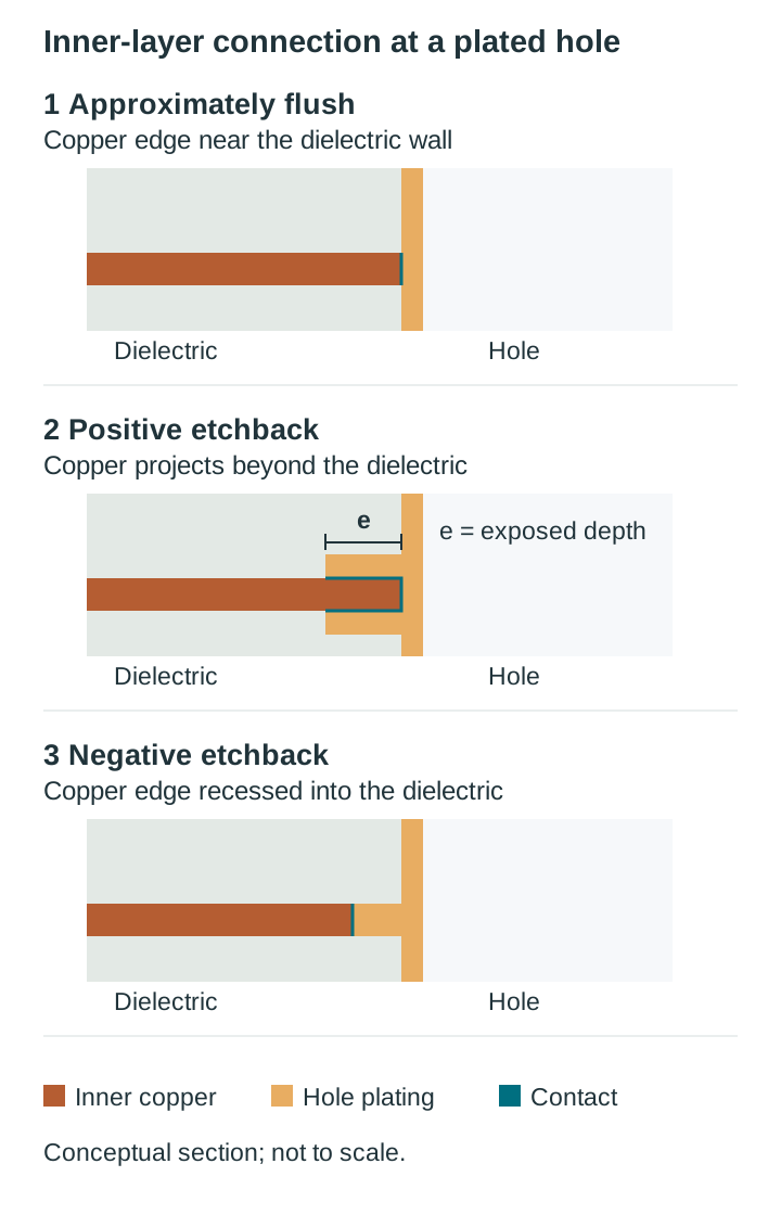
Simplified cross-sections, not to scale. Actual plating and interface geometry vary.
1. What Happens at the Hole Wall: Smear, Desmear and Etchback
Mechanical drilling can heat and soften resin locally, dragging it across exposed inner-layer copper. This film is smear. If resin remains between the land and the deposited copper, it can interfere with the copper-to-copper connection and contribute to an interconnect defect (ICD), including separation during later thermal exposure. Electrical testing alone may not reveal every latent interface problem.
The following simplified conditions describe the copper edge relative to the dielectric at a sectioned location. Actual geometry and plating contact can vary around and along a hole.
| Condition | Inner copper position relative to the dielectric wall | Possible plating contact | How the condition may arise |
|---|---|---|---|
| Approximately flush after desmear | Copper edge roughly level with the dielectric | Primarily at the exposed edge | Smear removal without appreciable dielectric recession |
| Positive etchback | Copper protrudes into the hole | Edge and exposed portions of the top and bottom faces | Dielectric removal beyond the copper edge |
| Negative etchback | Copper edge recessed behind the dielectric | Depends on the recess and deposited plating geometry | Relative removal of copper and dielectric during processing |
A recessed edge is not a premium version of etchback. Its significance depends on the observed geometry, plating and applicable acceptance criteria. A deep recess can make plating or solution removal more difficult and may be associated with voids or stress concentrations.
How much extra contact length might positive etchback expose?
The following is illustrative geometry, not a measurement or a standard requirement. Assume an ideal flush baseline, uniform copper thickness t, equal exposed lengths e on both faces, and plating in contact with every exposed surface. The idealized contact length in one cross-section is:
| Illustrative inner foil | Assumed t | Flush baseline | Hypothetical e = 0.013 mm | Hypothetical e = 0.025 mm |
|---|---|---|---|---|
| ½ oz | 0.018 mm | 0.018 mm (1.0×) | 0.044 mm (2.4×) | 0.068 mm (3.8×) |
| 1 oz | 0.035 mm | 0.035 mm (1.0×) | 0.061 mm (1.7×) | 0.085 mm (2.4×) |
| 2 oz | 0.070 mm | 0.070 mm (1.0×) | 0.096 mm (1.4×) | 0.120 mm (1.7×) |
In this idealized comparison, the same assumed etchback produces a larger relative increase for thinner foil. It does not establish plating quality, actual contact area, current capability or fatigue life. Those depend on the real geometry, materials, processing and evidence.
2. When to Consider Etchback or Desmear
Discuss the requirement with the customer, fabricator and quality representatives rather than selecting a route from a quality class alone.
| Situation | Question for the responsible parties | Engineering consideration |
|---|---|---|
| Customer, prime-contractor or legacy drawing addresses etchback | What do the applicable order and controlled documents require? | Requirements may flow down through the contract |
| Thin inner foils and expected thermal cycling | Is additional exposed land a design objective? | Idealized geometry shows a relative contact-length increase, not a demonstrated reliability benefit |
| High layer count with repeated assembly exposure | What interface evidence and process controls are appropriate? | Thermal expansion can load land-to-barrel interfaces |
| A class is named without an explicit etchback note | What does the specified revision and complete order require? | Do not infer the answer from the class label alone |
| Tight hole-wall or spacing constraints | What limits and trade-offs apply to the selected process? | Resin and glass removal can affect wall geometry and wicking |
| Unfamiliar or hybrid material system | What does the material-specific guidance and qualified fabrication procedure support? | Different dielectric layers can respond differently to treatment |
A vague “etchback required” note can leave the process and evidence open to interpretation. Equally, a flush-looking interface should not be accepted or rejected solely on the basis of a class label. Resolve the requirements and inspection plan before fabrication.
3. Acceptance Criteria: Use the Specified Revision and Order
IPC-6012 may be referenced in a rigid-board order, but this article does not interpret its requirements. The customer, supplier and quality representatives should consult the controlled revision and complete order actually specified, including any applicable drawings, test methods and flowed-down requirements.
| Topic to resolve | Questions for the responsible parties |
|---|---|
| Etchback | Is it required for this order? If so, what geometry, measurement method and criteria apply? |
| Smear and interfaces | What conditions must be evaluated, and how are they assessed? |
| Negative etchback and shadowing | What definitions and acceptance criteria apply to the observed conditions? |
| Related wall characteristics | Which plating, wicking, glass or wall-geometry requirements apply? |
| Sampling and conditioning | Which coupons or holes, sampling plan, conditioning and test methods does the order specify? |
| Disposition | Who decides whether the evidence meets the agreed criteria, and how are exceptions handled? |
Do not substitute generic numbers, a hypothetical contract or an averaged result for the actual order. The required evidence, including whether a section is conditioned or as-plated, must be established from the applicable documents and agreed inspection plan.
4. Process Options by Laminate
Hole-wall treatment must be matched to the exact resin system and fabrication procedure. The options below are process descriptions, not universal recommendations or acceptance criteria.
| Method | General mechanism | Selection considerations |
|---|---|---|
| Alkaline permanganate | Swelling and oxidation can remove susceptible resin | Response can vary with resin formulation, filler, bath condition and process controls |
| Plasma | Reactive species treat or remove selected material at the hole wall | Gas mix, cycle and effectiveness depend on the material and equipment; glass response differs from resin response |
| Combined plasma and wet chemistry | Sequential treatments address different process objectives | Sequencing and compatibility need to be established for the exact stackup |
| Glass etch | A separate chemistry can remove exposed glass | Use and control depend on the material, procedure and required wall condition |
| Acid treatments | Certain acids attack resin | Process suitability, handling and waste controls need specific review |
For a hybrid stackup, ask how the proposed process treats each material and how the agreed inspection plan will evaluate the result. Do not assume that PTFE or a hybrid construction always requires plasma.
Material-specific guidance can differ from a general process description. The Rogers RO4835T core / RO4450T bond guide advises that aggressive desmear is typically unnecessary for that specific combination, recommends against etchback of RO4000 cores and prepreg, and discusses inspection-based reduction when appropriate. Use that guidance only in its stated context; it does not override the actual contract or establish a route for other materials.
For AGC fastRise EZpure only, the manufacturer’s processing guide warns against permanganate desmear containing glass-etch chemistry because of excessive etchback risk and directs consultation with AGC if other stack materials require glass etch. The guide separately addresses glass-etch baths in electroless copper processing and states that those baths alone do not sufficiently desmear EZpure; it does not prohibit all glass-etch baths. The applicable material, controlled revision, complete stack and qualified process must be confirmed.
5. Reading a Microsection That Claims Etchback
A microsection provides a view at the location and plane sectioned. It can show useful local evidence, but it does not by itself establish the condition of an entire barrel or lot. The sampling, preparation, conditioning, measurements and acceptance criteria must be those specified or agreed for the order.
For background, see our PCB test coupons guide and microsection report guide.
| What to review | Questions to ask |
|---|---|
| Sample identification | Which board or coupon, hole and location were sectioned? How do they relate to the agreed sampling plan? |
| Preparation and conditioning | What preparation and any conditioning were performed? Do they match the applicable plan? |
| Etchback measurements | Where and how were depths measured, and what criteria apply? |
| Shadowing and negative etchback | What is visible at the evaluated locations, and how does the order define and assess it? |
| Interface appearance | Is the junction visible enough to assess? Does an apparent dark line need further investigation under the agreed procedure? |
| Wall and plating | What relevant dimensions or conditions were evaluated, using which methods and criteria? |
| Scope and disposition | What can this section support, what remains unknown, and who will make the disposition? |
Fictional worked review: a 12-layer coupon
This example is fictional arithmetic, not IPC text or an accepted generic criterion. Assume a hypothetical agreement calls for a minimum positive etchback of 0.010 mm at each evaluated location. It also defines how shadowing is assessed, but those fictional details are not supplied here.
The hypothetical coupon has a 0.30 mm drilled-hole diameter; its finished-hole diameter is unspecified. The following invented readings and observations refer to one visible hole-wall side in one section plane. No preparation or conditioning state is specified.
| Layer | Invented local etchback reading | Hypothetical local observation | Comparison with fictional minimum |
|---|---|---|---|
| L2 (½ oz) | 0.012 mm | No shadowing observed at the evaluated location | At or above 0.010 mm |
| L3 (1 oz plane) | 0.009 mm | Shadowing observed | Below 0.010 mm |
| L6 (½ oz) | 0.004 mm | No shadowing observed at the evaluated location | Below 0.010 mm |
| L7 (1 oz plane) | 0.011 mm | No shadowing observed at the evaluated location | At or above 0.010 mm |
| L10 (½ oz) | 0.015 mm | No shadowing observed at the evaluated location | At or above 0.010 mm |
The five readings average 0.0102 mm, but that average does not replace the fictional per-location comparison: L3 and L6 are below the assumed minimum. The shadowing observation also requires assessment against the fictional agreement’s criteria, which are not shown.
The two hole-wall sides in a vertical section are distinct from the top and bottom faces of an inner conductor. The hypothetical shadowing observation does not identify a conductor face or establish the opposite wall’s condition.
An actual decision would need the applicable order, actual preparation and measurement method, calibration and uncertainty. These fictional comparisons alone do not establish an actual result, cause, lot status or disposition.
6. Cost, Lead Time and Risk Trade-Offs
- Process time: Additional treatment or a separate process step may affect the quote and schedule. Ask what the selected route entails.
- Inspection load: Coupon preparation, conditioning and measurement can add time and panel area, depending on the agreed plan.
- Wall quality: Resin or glass removal can change wall geometry and may affect wicking or other concerns. Evaluate the trade-offs for the design and process.
- Potential benefit: The idealized contact-length calculation is useful for discussing geometry, but it is not proof that etchback will improve a particular board’s performance.
7. RFQ Checklist for Etchback or Desmear
Use the RFQ to resolve requirements and evidence before production:
- Identify the controlled documents: Name the applicable specification revision, order, drawings and any flowed-down requirements. Ask the responsible parties to determine what they require.
- Describe the desired outcome: State any project-specific etchback or hole-wall objective and have the customer, supplier and quality representatives agree on applicable criteria. Do not present hypothetical values as IPC requirements.
- Name the exact materials: Include core, bond and prepreg designations, as well as the stackup and relevant material guidance.
- Discuss the proposed process: Ask how it is matched to the materials and fabrication procedure, including any treatment of hybrid layers.
- Agree on inspection: Resolve sample identification, coupon and hole selection, conditioning, measurement locations and reporting against the applicable order.
- Agree on disposition: Identify who reviews exceptions and decides whether further investigation or action is needed.
You can ask HILPCB about project-specific process, inspection and evidence details for multilayer PCBs or PTFE and RF laminates. For related background, see our IPC-6012 overview and IPC Class 1, 2 and 3 comparison. Include your drawing and stackup with a quote request and ask what can be offered for the particular project.
FAQ
Is etchback the same as desmear?
No. Desmear removes resin smear from exposed inner-layer copper. Positive etchback removes dielectric beyond the copper edge and can expose portions of the land’s faces. The process selected depends on the exact material, fabrication procedure, order and inspection evidence; neither route should be assumed for every multilayer PTH.
Does IPC-6012 Class 3 require etchback?
Do not determine that from the class label alone or from this article. The responsible parties should consult the controlled revision and complete order specified for the project, including drawings and flowed-down requirements.
What is negative etchback, and is it a defect?
Negative etchback describes a copper edge recessed behind the dielectric at an evaluated location. Whether an observed recess is acceptable depends on the applicable criteria and associated evidence, including the plating condition. The responsible parties should assess it against the specified revision and order.
Why might plasma be considered for PTFE or polyimide boards?
Plasma can be one option for treating certain materials or stackups, but suitability depends on the exact material, equipment, fabrication procedure, order and inspection evidence. PTFE, polyimide and hybrid boards do not automatically require a plasma route.
How do I verify that etchback was achieved?
Agree on an inspection plan with the customer, supplier and quality representatives using the specified order and controlled documents. Review the identified samples, preparation, any required conditioning, measurement locations and applicable criteria. A microsection is local evidence; its adequacy and any disposition depend on the agreed plan, not on a universal rule that one section condition is sufficient or insufficient.