
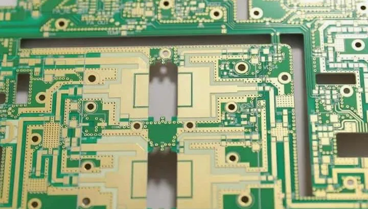
A Rogers PCB uses a specified Rogers laminate or hybrid construction for its RF, thermal or mechanical requirements. Ask HILPCB to review the exact grade, copper, bonding system, via route and acceptance plan; the family name does not establish support for every construction or test.
If your next-generation electronic system requires low signal loss, thermal stability, and tight impedance control, a Rogers-laminate PCB may be suitable. HilPCB PCB can review the specified material, stack-up, manufacturability, and test requirements during RFQ.
Market Applications and Strategic Use Cases
Rogers PCB materials are engineered for industries where RF performance and environmental stability are non-negotiable.
- Automotive radar (e.g., 77GHz, 79GHz) may use RO4000-series or other qualified low-loss laminates for their dimensional and dielectric consistency.
- 5G base stations and mmWave modules may use TMM, RO4000 or other suitable RF laminates; selection depends on the loss, thermal and manufacturing constraints.
- Aerospace and defense systems—such as satellite comms and phased array antennas—may use suitable RT/duroid or other qualified materials for ultra-stable performance in extreme environments.
- Medical RF equipment, including MRI subsystems, may use suitable RF laminates for electrical performance. A laminate choice does not establish patient-contact biocompatibility or finished-device approval.
- Scientific and industrial RF instruments demand the low-loss, stable characteristics Rogers materials provide at GHz and mmWave frequencies.
Qualify the finished construction against each application’s electrical, environmental and approval requirements.
Rogers PCB Material Types and Performance Benefits
Rogers Corporation offers a range of RF-optimized materials. Each series meets specific design needs:
- RO4000 Series (e.g., RO4350B): Suitable for many RF constructions where loss and manufacturability are balanced. For standard RO4350B, Rogers lists process Dk 3.48 ± 0.05 at 10 GHz, design Dk 3.66 and typical Df 0.0037 at 10 GHz; the process test is clamped stripline at 23°C, while the design value uses differential phase length over 8–40 GHz. Check thickness-specific exceptions, including 4 mil material; 40 GHz is not a universal operating limit.
- TMM Series: Ceramic-filled thermoset composite laminates designed for power amplifiers and beamforming units. TMM 10i, for example, has high thermal conductivity (confirm the value and method against the exact grade datasheet) and exceptional electrical stability.
- RT/duroid Series: PTFE-based grades may suit low-loss RF circuits. RT/duroid 5880 lists process Dk 2.20 ± 0.02 at 10 GHz/23°C by clamped stripline; verify the grade’s tolerance, frequency, copper and application qualification.
- CLTE Series: Offers grades with controlled expansion; hybrid bonding still requires compatible materials and a qualified process.
- AD and DIALAM Series: Compare the exact antenna or multilayer grade, processing guidance and availability rather than selecting by family alone.
Choosing the right material depends on your operating frequency, power density, form factor, and budget. Our engineering team helps you match material specs to real-world performance needs.
Design Rules and Engineering for Rogers PCBs
Rogers PCBs require a tailored design approach that goes beyond standard FR-4 layouts. At HilPCB PCB, we guide our clients through:
- Stack-up optimization: Multilayer stack design must align dielectric and copper layer thicknesses for target impedance.
- Impedance control: Rogers materials require tight tolerance control and careful field simulation to ensure signal integrity at high frequencies.
- Via reliability: PTFE-based substrates expand differently than FR-4; via design must prevent cracking under thermal cycling.
- Thermal engineering: Use the exact grade’s conductivity in a complete heat-path model, including copper, vias, interfaces and enclosure cooling.
- Surface finish: Evaluate conductor loss, solderability, corrosion and assembly requirements for the chosen copper and finish; a laminate family alone does not select ENIG, OSP or immersion silver.
- Mixed dielectric handling: In hybrid PCBs (Rogers + FR-4), proper bonding prep and lamination strategy are essential.
Design-for-manufacturability (DFM) is especially important here—early collaboration saves cost and boosts yield.
Manufacturing Considerations and Process Control
HILPCB fabricates and assembles high-frequency boards using Rogers RO4000 (including RO4350B), TMM and RT/duroid (including RT/duroid 5880) families, subject to the exact grade and construction review. Grade-specific finish and process adjustments, dedicated qualified drilling/routing/lamination routes, RF tests, microsections and dimensional inspection can be included. Our prototype-to-volume service supports aerospace, telecom, automotive and industrial applications from material selection through final assembly and test. FCT, programming and enclosure integration can be coordinated as a one-roof delivery route when defined in the quote.
Processing depends on the resin family and construction. Many RO4000 operations use FR-4-compatible techniques, while PTFE grades require different hole preparation:
- Precision drilling: Select tooling, speed, chip load and debris removal for the exact PTFE or ceramic-filled construction; inspect hole walls and qualify metallization.
- Routing and milling: Match tool geometry, wear limits and feed to the exact material, reinforcement and edge requirements.
- Lamination: Qualify the bonding layer, fill, pressure and measured thermal profile. A thermoset core is not melted to bond the stack; hybrid FR-4 compatibility needs review.
- Plating and adhesion: Additional surface treatments are often needed for copper adhesion, especially on low-surface-energy substrates.
- Testing: Continuity/isolation tests do not establish GHz performance. Agree high-frequency RF testing, fixtures, calibration, microsections and dimensional acceptance as required, identifying the provider and applicable standard.
Confirm the proposed site, material availability, qualified process route and quantity-specific capacity during quotation.
Cost Drivers and Value Optimization
Compare the total quoted construction rather than assuming a fixed Rogers-versus-FR-4 premium. Material prices are only one part of the picture:
- Material cost: Rogers substrates are more costly than standard FR-4 in many constructions; obtain current material quotations and compare finished-board stackups, depending on the series.
- Process complexity: Construction-specific drilling, bonding and metallization can affect time and tooling; RO4000 and PTFE routes differ.
- Yield impact: Tight geometries or unfamiliar constructions can increase scrap and rework risk; review actual process capability and DFM findings.
- Volume: Small runs may carry high setup costs. Larger volumes allow economies of scale.
A suitable material can support the following design goals, but verify each against a comparable system baseline and total quote:
- Better signal integrity
- Lower power consumption
- Smaller device footprints
- Improved reliability
We work closely with clients to find the optimal balance between performance and cost.
Choosing the Right Manufacturing Partner
Manufacturing Rogers PCBs is not for every shop. You need a supplier with:
- Rogers material identification and processing controls (confirm any claimed authorization separately)
- Proven design consultation for hybrid and RF stack-ups
- Advanced process control for drilling, lamination, and plating
- Reliability testing for high-frequency and thermal performance
- Global sourcing and scalability for large and small projects alike
For a HILPCB RFQ, provide the stackup, exact material/copper grades, drawing, via construction, quantity, assembly needs and test evidence. Confirm any claimed authorization, equipment or application qualification separately.
Ready to Build with Rogers PCB?
If you're developing radar systems, 5G modules, satellite transceivers, or any mission-critical RF equipment, HilPCB PCB can help.
Agree fabrication, assembly, programming, enclosure and RF-test responsibilities individually. Confirm which operations are internal or external, and the acceptance reports, change control and delivery milestones for the actual order.
Include modeled impedance/loss targets, coupon geometry and measurement reference planes so the manufacturing review can connect the design assumptions to verifiable acceptance.