
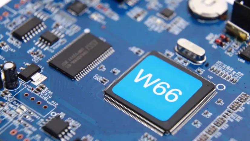
SMT assembly: Meeting real-time and safety-redundancy demands in industrial robotics control PCBs
In the Industry 4.0 era, industrial robots have become the core of automated production lines. As the “nervous system,” the control PCB largely determines precision, speed, and reliability. As an industrial networking engineer focused on EtherCAT, PROFINET, and CANopen real-time communications, I know deterministic networks succeed or fail not only because of the protocol, but because of their physical carrier—the manufacturing quality of the PCB. Here, SMT assembly is the critical bridge between design and reality. A tiny solder-joint defect, placement offset, or improper thermal processing can cause communication jitter, clock drift, or even system collapse. To handle the harsh constraints of industrial robot control, you must start with precision SMT assembly and ensure every step—from design review to final protection—is executed without gaps.
This article discusses the core technical challenges industrial robotics control PCBs face during SMT assembly, explains why real-time protocols impose special assembly requirements, and shows how strict process controls such as DFM/DFT/DFA review and First Article Inspection (FAI)—plus post-processing like Conformal coating—help deliver strong performance and long-term reliability.
EtherCAT/PROFINET clock sync and jitter control: why SMT assembly must be precise
Industrial Ethernet protocols like EtherCAT and PROFINET IRT are powerful because of precise clock synchronization. EtherCAT uses Distributed Clocks (DC), while PROFINET IRT relies on IEEE 1588 PTP. Both can reach sub-microsecond synchronization—yet this level of precision demands extremely high physical quality, especially in SMT assembly.
1. Crystal oscillator and clock-circuit assembly accuracy The clock source is the “heart” of synchronization. Any frequency error or Jitter can propagate and amplify through the network. During SMT assembly:
- Placement accuracy: Crystal Oscillator and load capacitors must follow placement rules strictly. Small offsets change parasitic capacitance and can shift clock frequency.
- Reflow profile control: peak temperature that is too high/low, or an improper ramp rate, can permanently damage crystals or cause frequency drift. Sensitive parts require tightly controlled profiles.
- Solder paste volume control: too much/too little paste affects mechanical strength and electrical connectivity, and can even cause tombstoning—fatal for dense clock circuits.
2. Differential clock equal-length and symmetry High-speed differential clocks (e.g., PTP clock pairs) are extremely sensitive to symmetry. After PCB fabrication, SMT assembly becomes the last gate to preserve that symmetry. Any disturbance from nearby components can break impedance matching, introduce common-mode noise, and increase clock jitter. That’s why DFM/DFT/DFA review must evaluate not only PCB layout, but also assembly impacts such as heat from adjacent large parts or mechanical stress. A complete DFM/DFT/DFA review is the first step to aligning manufacturability and performance.
Physical-layer design: SMT assembly challenges for PHY, magnetics, and connectors
The PHY is the bridge between the digital system and the physical cable. Assembly quality directly affects signal integrity and network stability. For industrial robots that move frequently and experience vibration, physical-interface reliability is non-negotiable.
1. PHY + magnetics placement and soldering Ethernet PHY, Magnetics, and RJ45 form a standard Ethernet interface. Their assembly has special constraints:
- Channel symmetry: magnetics include multiple windings for TX/RX differential pairs. Routing from PHY → magnetics → connector must keep strict equal-length and symmetry. SMT assembly must align magnetics pins and pads precisely to avoid asymmetry caused by placement/solder offset.
- Thermal management: PHY runs hot at high speed. If the Thermal Pad develops Voiding during reflow, heat transfer drops, leading to overheating, performance loss, or failure. This requires stencil and process optimization.
- Component isolation: analog (magnetics side) and digital (PHY side) must be well isolated to prevent digital noise coupling. During assembly, keep the isolation “moat” clean—no solder/flux residue that could create unintended noise paths.
2. Strict First Article Inspection (FAI) For such complex interface circuits, First Article Inspection (FAI) is mandatory. Before mass production, perform electrical test, dimensional checks, and X-Ray inspection on the first assembled PCBA to confirm SMT assembly faithfully implements the design intent. For example, X-Ray checks solder-joint quality on magnetics and PHY BGA, ensuring no shorts, opens, or internal voids. A successful First Article Inspection (FAI) is the foundation for stable quality at scale.
Industrial Ethernet interface assembly flow
- DFM/DFA review: Analyze PHY/magnetics/connector layout before production; optimize pad design and spacing to ensure assembly feasibility and reliability.
- Precision solder paste printing: Use a laser-cut step stencil to deliver accurate paste volume for fine-pitch PHY pins and larger magnetics/connector pins.
- SPI (solder paste inspection): 100% 3D SPI to confirm paste volume/area/height stays within the process window for every pad.
- High-accuracy placement: Use vision alignment to keep placement accuracy within ±0.03mm for critical parts such as PHY and crystals.
- Multi-zone reflow: For mixed boards with large connectors and tiny passives, use an optimized 10–12-zone profile to achieve ideal soldering temperature for all parts while avoiding heat-stress damage.
- AOI and X-Ray inspection: Run post-reflow AOI and X-Ray (for BGA/QFN) to confirm solder-joint quality.
EMC design: SMT assembly strategies for ESD, surge, and common-mode noise protection
Industrial environments are full of EMI, including EFT pulses from motor switching, ESD, and surge events. Control PCBs must deliver strong EMC capability—and the assembly quality of protection parts often decides whether the protection works.
- Protection-part placement rules: TVS diodes, MOVs, and gas discharge tubes must follow the “close to the connector” rule—place and assemble them as close as possible to the I/O connector. In SMT assembly, ensure these devices are placed at the very front of the signal entry; any extra trace length adds parasitic inductance and weakens protection.
- Common-mode choke assembly: common-mode chokes require correct differential in/out orientation. Reversing them can severely degrade signals. AOI must include polarity/orientation checks for direction-sensitive parts.
- Ground-path optimization: protection parts need a low-impedance ground path to dump transient energy. During assembly, ensure ground pads connect well to the plane, with full joints and no voids. For high-current discharge parts like GDTs, pad design and solder quality directly affect system safety.
To further improve protection in harsh environments, Conformal coating becomes critical. It forms a tough protective layer over the PCBA, resisting moisture, dust, and salt spray, preventing shorts or corrosion from environmental factors—and improving EMC robustness and long-term reliability. Selecting the right Conformal coating material and process is a standard requirement for industrial-grade products.
Timing and real-time behavior: hardware-software co-design around buffering, interrupts, and drivers
Real-time communication depends on both hardware and software (drivers, stack) working together. The processor relies on interrupts, DMA, and internal Buffer/Queue mechanisms to process packets efficiently; any delay breaks determinism.
The SMT assembly impact here is the ability to assemble high-density, high-performance silicon reliably.
- BGA/LGA challenges: modern industrial-control SoCs and FPGAs typically use BGA or LGA with hundreds or thousands of pins and very fine pitch. This requires extreme SMT assembly precision and control: coplanarity, uniform paste printing, reflow temperature uniformity, and post-reflow X-Ray capability are prerequisites.
- Power integrity (PI): high-speed ICs are sensitive to power cleanliness. Many decoupling capacitors must sit close to power pins for transient current. Assembly must ensure high-quality soldering of small packages (often 0201 or 01005). Lower mounting inductance means better filtering.
For these highly integrated, complex projects, choosing Turnkey PCBA is often the most efficient approach. Providers like HILPCB integrate PCB fabrication, component sourcing, SMT assembly, and test to ensure smooth handoffs and consistent quality—delivering validated, high-reliability products without forcing customers to manage a complex supply chain.
High-density BGA assembly reminders
- Pad design (NSMD): NSMD pads are recommended to improve solder-joint reliability and stress relief.
- Solder paste selection: Use finer powder (e.g., Type 4 or Type 5) to match fine-pitch BGA stencil apertures.
- Nitrogen reflow: Reflow in N2 improves wetting and reduces oxidation, which is especially important for lead-free processes.
- 3D X-Ray inspection: For PoP (Package on Package) or underfilled BGAs, use 3D X-Ray or CT to verify internal joints (e.g., Head-in-Pillow and voiding).
Reliability and environmental robustness: from FAI to final protection
Industrial robots often run 7x24 in harsh environments. Control PCBs must deliver high reliability and strong environmental robustness—requiring a complete quality assurance system from design to final protection.
1. Design-manufacturing consistency
- DFM/DFT/DFA review: early DFM/DFT/DFA review helps identify and resolve manufacturing/assembly risks, such as planning DFT test points for post-assembly functional test and evaluating DFA placement for automated assembly and rework.
- First Article Inspection (FAI): strict First Article Inspection (FAI) ensures the first build is correct and sets the gold standard for subsequent production.
2. Ultimate protection for extreme conditions When robots face humidity, chemicals, strong vibration, or extreme temperatures, standard protection may not be enough:
- Conformal coating: a cost-effective choice for moisture/dust protection, preventing failures from condensation or contamination.
- Potting/encapsulation: for severe shock, vibration, or chemical corrosion, Potting/encapsulation provides the highest level of protection by fully encapsulating the PCBA in epoxy or polyurethane, improving isolation and mechanical strength.
Whether you choose Conformal coating or Potting/encapsulation, plan it in the design stage because these processes affect thermal performance, weight, and serviceability.
Conclusion
Industrial robotics control PCB performance and reliability are a system-engineering outcome—not simply a matter of picking better chips or writing better software. High-quality SMT assembly is the physical foundation: from precision clock circuitry that enables EtherCAT/PROFINET synchronization, to robust physical-layer interfaces that protect signal integrity, to EMC protection-part placement and soldering—every detail depends on rigorous SMT assembly control.
By implementing comprehensive DFM/DFT/DFA review, running strict First Article Inspection (FAI), and selecting the right Conformal coating or Potting/encapsulation strategy, you can build a truly reliable “robot brain.” Choosing a partner like HILPCB with full Turnkey PCBA capability turns complex engineering constraints into reliable products—and helps you win in a competitive market. Ultimately, excellent SMT assembly is the key to high performance, high reliability, and long lifecycle in industrial automation systems.
Common Questions
Why are robotics control PCBs especially demanding?
They combine real-time control, motion interfaces, power sections, and long-life reliability requirements in harsh industrial environments.
How do DFM, DFT, DFA, and FAI reduce launch risk?
They catch manufacturability gaps, test-coverage problems, and first-build deviations before those issues spread into pilot or volume production.
When are conformal coating or potting needed?
They are used when boards must resist moisture, dust, vibration, chemicals, or electrical stress in demanding factory conditions.
What should buyers look for in an SMT assembly partner?
Proven process discipline, industrial reliability experience, and turnkey support from prototyping through lifecycle production are key.