
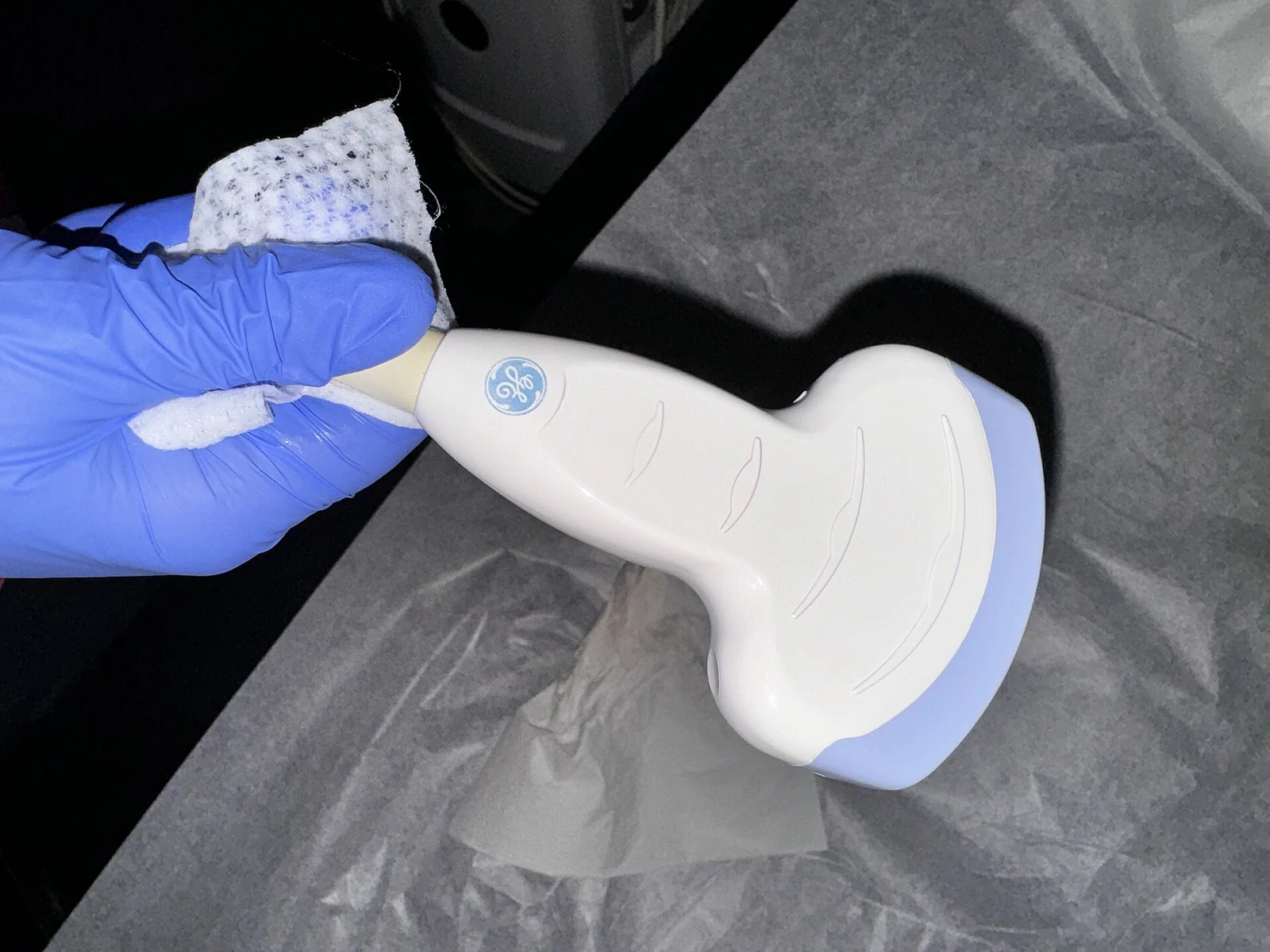
- The first thing to freeze in ultrasound-probe PCB material selection is not the name of a supposedly premium laminate, but whether the probe structure, front-end noise limits, flex life, and cleaning workflow allow that material system to stay stable over time. Without those boundaries, datasheet material names have little engineering meaning.
- Material problems on probe boards rarely show up completely in the first electrical check. They often emerge later through bend cycling, humidity exposure, cleaning and reprocessing, potting, and lot changes.
- Low-noise stability matters more than a low-loss label. For an ultrasound front end, surface insulation after moisture exposure, leakage after residue, and channel-to-channel consistency over time often affect imaging performance earlier than one dielectric number on paper.
- If the probe includes a flex or rigid-flex region, life has to drive material selection. IPC-6013C is the qualification and performance specification for flexible printed boards, which means flex regions, coverlay, adhesive system, and stiffener boundaries cannot be treated with the same assumptions as a rigid board.
- In medical projects, the material system has to be defined together with cleaning, reprocessing, and traceability. FDA's public guidance on reprocessing reusable devices makes it clear that reprocessing instructions require scientific validation, so material compatibility is not an afterthought. It is a design input.
Quick Answer
The core of ultrasound-probe PCB material selection is not choosing a board that sounds more advanced. It is proving that the chosen material system stays stable across front-end low-noise behavior, rigid-flex life, cleaning and reprocessing, assembly, and lot changes. On a medical probe project, freezing structure and validation logic early is usually more effective than changing materials late.
Table of Contents
- What should engineers review first in ultrasound-probe PCB materials?
- Summary table of key rules and parameters
- Why should probe structure be defined before material grade is discussed?
- Why does low-noise stability matter more than marketing labels?
- Why must flex and rigid-flex regions be driven by lifetime?
- Why should cleaning compatibility, traceability, and validation be frozen together?
- Next steps with HILPCB
- Frequently Asked Questions (FAQ)
- Public references
- Author and review information
What should engineers review first in ultrasound-probe PCB materials?
Start with structural boundaries, low-noise stability, flex life, cleaning compatibility, and traceability requirements.
This does not mean "medical projects should automatically choose the most expensive material," and it does not mean "if the probe powers up, the material must be right." The public IEC 60601-1-2 context ties EMC to essential performance in medical electrical equipment. IPC-6013C directly covers flexible-board qualification and performance. FDA's guidance on reprocessing reusable medical devices explicitly requires scientific validation of reprocessing instructions. Put together, those public frameworks lead to one practical conclusion: probe PCB materials must simultaneously support electrical stability, mechanical life, and post-processing compatibility.
The five questions worth answering before design freeze are usually:
- Is the probe a rigid board, a flex interconnect, or a Rigid-Flex PCB?
- Which regions are front-end low-noise areas, bend zones, connector zones, and potting zones?
- Does the material stay stable under cleaning, baking, reprocessing, and humidity exposure?
- Do flex copper, coverlay, adhesive system, and stiffeners match the life target?
- Are lot traceability, material change control, and revalidation triggers already defined?
If the project is still comparing rigid-only, flex-interconnect, and rigid-flex routes, it is usually better to bring the process limits of Rigid-Flex PCB and Flex PCB into the structural review early instead of deciding the material route late in layout.
Summary table of key rules and parameters
| Rule / Parameter | Recommended range or judgment method | Why it matters | How to verify | What happens if ignored |
|---|---|---|---|---|
| Structure first | Define rigid, flex, connector, and potting zones first | Decides whether the material matches the real structure | Structural review, stackup review | The material route proves mismatched later |
| Low-noise stability | Look at moisture uptake, residue, surface insulation, and long-term consistency | Ultrasound front ends suffer more from drift and leakage | Electrical checks after humidity exposure, noise comparison | First article is fine, later channels drift |
| Flex lifetime | Bend zones are defined jointly by copper, coverlay, adhesive, and stiffener | Flex regions hide latent failures most easily | Bend cycling, cross-section, visual inspection | Intermittent opens and hidden cracks |
| Cleaning compatibility | Material must match cleaning, baking, coating, and reprocessing | Medical post-processing cannot be patched in later | Cleaning validation, residue analysis | Corrosion, leakage, and validation failure |
| Traceability and change control | Material lots and supplier changes must be tied to validation | Medical projects cannot tolerate unprovable equivalence | Document review, lot tracking | Scale-up cannot prove sameness |
| Assembly window | Pad flatness, coverlay edge, and final-assembly interface should be reviewed together | Probe final assembly amplifies material issues | First-article review, final-assembly check | Stress rises, rework gets harder |
| Typical evaluation case | Better first priority |
|---|---|
| Small rigid front-end board | Low-noise stability, cleaning residue, surface insulation |
| Flex interconnect to cable | Bend life, stiffener strategy, stress transfer |
| Rigid-flex probe board | Transition-zone life, potting compatibility, traceability rules |
Why should probe structure be defined before material grade is discussed?
Conclusion: Because whether a material is suitable depends on which physical region it serves, not on how advanced its name sounds.
An ultrasound probe usually includes a sensitive front-end signal area, a flex transition zone, a connector or cable zone, a potting zone, and mechanical enclosure constraints. Unless those region boundaries are defined first, talking about FR-4, PI, coverlay, or one adhesive system by itself lacks real context.
The points worth freezing first are:
- Which regions must remain rigid and geometrically stable
- Which regions must absorb bending or assembly stress
- Which regions are most sensitive to surface insulation, contamination, and leakage
- Which regions will see potting, cleaning, reprocessing, or long-term chemical exposure
If the probe structure clearly needs a flex transition, it is usually worth bringing the process windows of Flex PCB and Rigid-Flex PCB into the review early instead of extending rigid-board assumptions by default.
Why does low-noise stability matter more than marketing labels?
Conclusion: Because what an ultrasound front end really has to protect is not the material label, but whether weak echo signals stay stable over long-term environmental change.
IEC 60601-1-2 places essential performance and electromagnetic disturbance inside the same public framework for medical electrical equipment. On a probe PCB, that means base noise, immunity, surface insulation, and residue control all belong to system performance rather than to peripheral process detail.
The items worth prioritizing are:
- Whether the material increases leakage or drift after humidity, storage, and cleaning
- Whether surface residue affects high-impedance front-end nodes
- Whether channel-to-channel consistency is sensitive to lot-to-lot material or process variation
- Whether reference grounding, shielding, and surface condition remain stable together
If the project is entering front-end board sampling, it is usually more useful to validate the key zones during PCB Prototype than to choose material from the datasheet alone.
Why must flex and rigid-flex regions be driven by lifetime?
Conclusion: Because the most typical latent failures in probe products usually happen in bend zones and rigid-flex transition zones, not in static electrical tests.
IPC-6013C is the qualification and performance specification for flexible printed boards, which by itself signals that flexible structures have to be managed explicitly by life, stress, and performance. On an ultrasound probe, copper type, coverlay, adhesive system, stiffener design, and bend direction all directly affect whether hidden cracks, intermittent opens, and unstable signals will appear later.
The points worth reviewing first are:
- Whether the routing direction in the bend zone matches the mechanical motion direction
- Whether flex copper, coverlay, and adhesive system fit the intended life target
- Whether stiffeners and connector boundaries create new stress concentration
- Whether potting or final assembly adds extra constraints into the bend region
If the board will later enter complex SMT and final probe assembly, it is usually worth bringing the flatness and assembly-stress behavior of SMT Assembly into the flex-region review at the same time.
Why should cleaning compatibility, traceability, and validation be frozen together?
Conclusion: Because many material problems in medical probes are not that the device cannot work once. The real problem is that the team cannot prove it will work repeatedly over time.
FDA's reprocessing guidance explicitly states that reprocessing instructions for reusable medical devices require scientific validation. FDA's public explanation of reprocessing quality also says cleaning validation should consider clinically relevant soil, worst-case soiling, and residual-soil measurement. For a probe PCB, that means material compatibility cannot be judged only by whether one cleaning cycle works. It must be defined together with reprocessing, residue control, and lot-change handling.
A practical pre-release freeze normally includes:
- Material-system freeze. Board material, copper, coverlay, adhesive system, and finish become one controlled version.
- Cleaning-compatibility freeze. Cleaning, baking, coating, potting, and material compatibility are explicitly defined.
- Life-validation freeze. Bend cycle, thermal cycling, humidity exposure, and electrical test method are all defined.
- Traceability-rule freeze. Material lot, supplier switch, and revalidation triggers are defined.
- Document-version freeze. Structure, material, assembly, and validation all follow one revision logic.
If the project is already close to pilot build or formal medical validation, it is usually better to organize those inputs directly into a joint engineering package for PCB Manufacturing, SMT Assembly, and Quote / RFQ rather than leaving the validation boundary distributed across different teams.
Next steps with HILPCB
If you are currently working on an ultrasound probe, a medical front-end capture board, or another low-noise medical electronic with flex interconnect, the next step is usually to turn "the material looks suitable" into "the structure, lifetime, and cleaning limits can actually be proven."
- When the main issue is flex interconnect and rigid-flex transition, compare Flex PCB and Rigid-Flex PCB first.
- When the project is more sensitive to front-end noise and surface condition, push the key regions into PCB Prototype for early validation.
- When material, coverlay, final assembly, and flatness directly affect assembly, bring SMT Assembly into the review at the same time.
- When manufacturing, cleaning, and reprocessing limits need to be defined early, organize those inputs with PCB Manufacturing.
- When structure, material, validation matrix, and traceability rules are frozen, move them into Quote / RFQ for the next engineering handoff.
Frequently Asked Questions (FAQ)
Is low loss alone enough when choosing an ultrasound-probe PCB material?
A: No. For a probe front end, low-noise stability, surface insulation after humidity, cleaning compatibility, and flex life matter just as much.
Why do many probe-material problems not show up in the first electrical test?
A: Because many real risks come from bend cycling, humidity exposure, cleaning residue, reprocessing, and lot changes rather than from a simple power-on event.
What is most often underestimated in rigid-flex probe regions?
A: The combined effect of copper type, coverlay, adhesive system, stiffener design, and potting boundary on stress and lifetime.
Why must medical projects bring cleaning compatibility into material selection so early?
A: Because reusable or reprocessed medical devices must validate their reprocessing instructions, and material incompatibility will show up directly during formal validation.
What is most worth freezing before fabrication?
A: Freeze probe structure, material system, rigid-flex lifetime logic, cleaning compatibility, validation matrix, and traceability rules first.
Public references
IEC 60601-1-2:2014 | Medical electrical equipment - EMC - Requirements and tests
Supports the article's explanation that low-noise stability on medical electrical equipment should be understood together with EMC and essential performance.IPC-6013C Qualification and Performance Specification for Flexible Printed Boards
Supports the article's explanation that flexible boards, bend zones, and rigid-flex transitions cannot be treated like ordinary rigid boards.Reprocessing Medical Devices in Health Care Settings: Validation Methods and Labeling | FDA
Supports the article's explanation that reusable medical devices require scientifically validated reprocessing instructions, so material compatibility should be treated as an early design input.Factors Affecting Quality of Reprocessing | FDA
Supports the article's discussion that cleaning validation should consider clinically relevant soil, worst-case soiling, and residual-soil measurement.
Author and review information
- Author: HILPCB medical electronics and flex-board content team
- Technical review: reliability, PCB process, and assembly engineering team
- Last updated: 2026-05-25